

ALF18
-
Content Count
3,823 -
Joined
-
Last visited
Content Type
Profiles
Forums
Calendar
Posts posted by ALF18
-
-
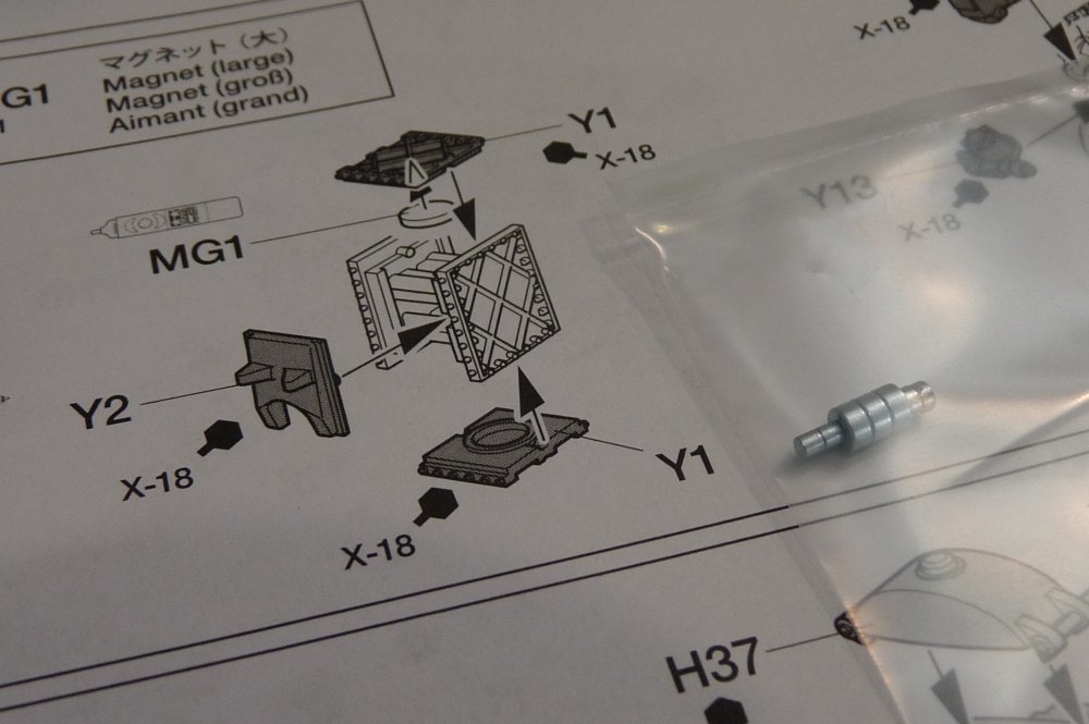
This next step is a bit tricky. The first time I glued the two side parts together (the ones shown assembled already in this step), I got them wrong. The diagram was not conclusive to me, so I ended up putting them 180 degrees out from where they should be. At that point, I had been called upstairs to mash some potatoes, a request which I never refuse if I want to stay married.
The glue had time to dry on the poorly-orientated parts before I noticed it. It was only when I dry-fit one of the Y1 parts in place that I noticed it was at an angle, which is not correct. Luckily, I am using Tamiya extra-thin cement. A quick application of some drops of the same cement, and very quickly the parts came apart without damaging anything. I swapped the two parts around 180 degrees, and found that Y1 fit perfectly onto one end at a 90 degree angle. Phew.
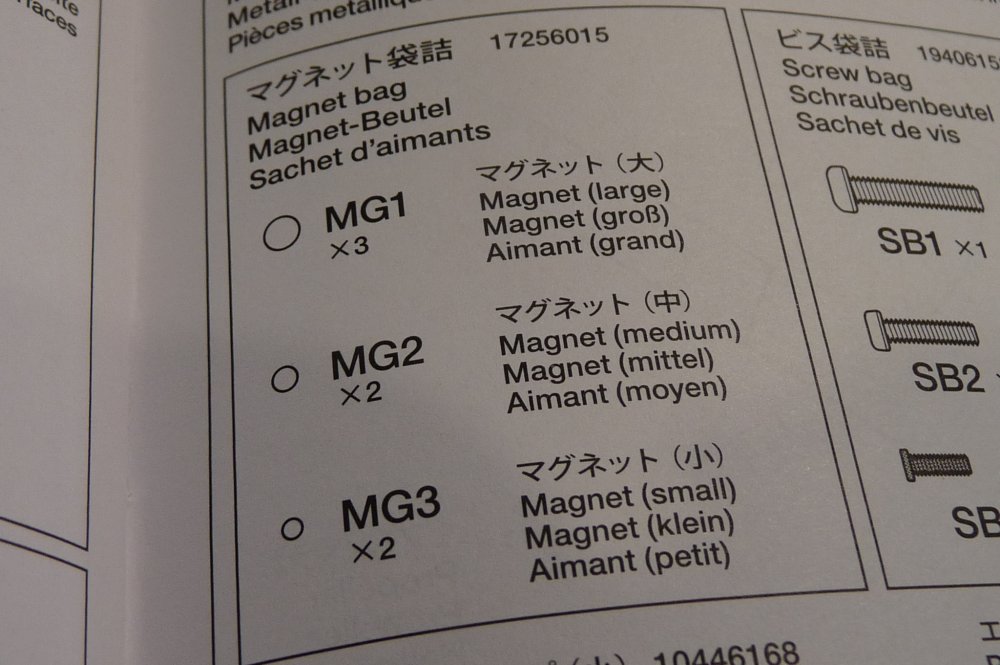
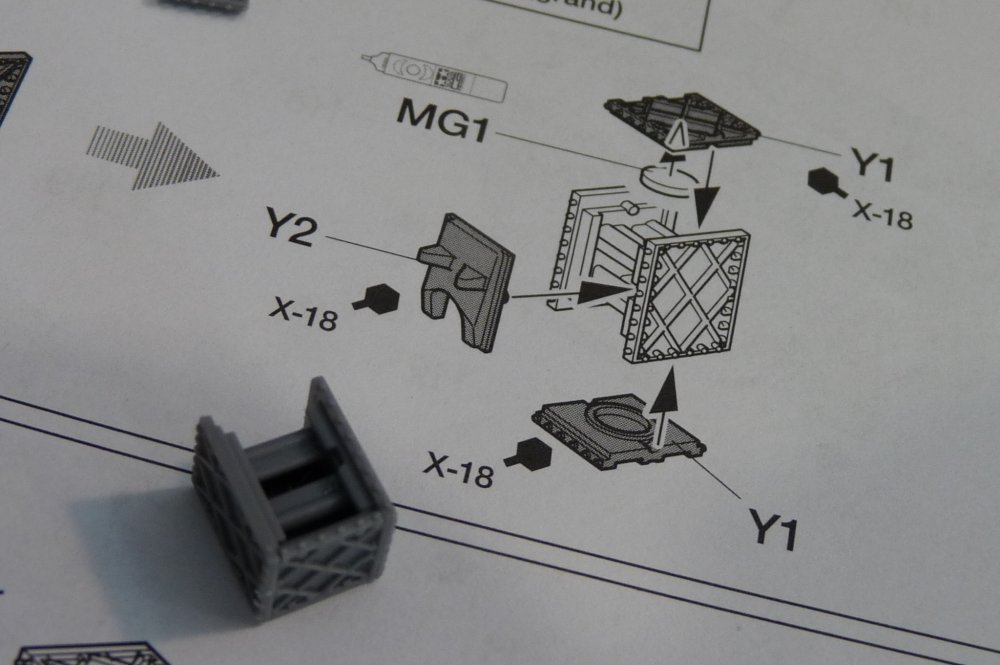
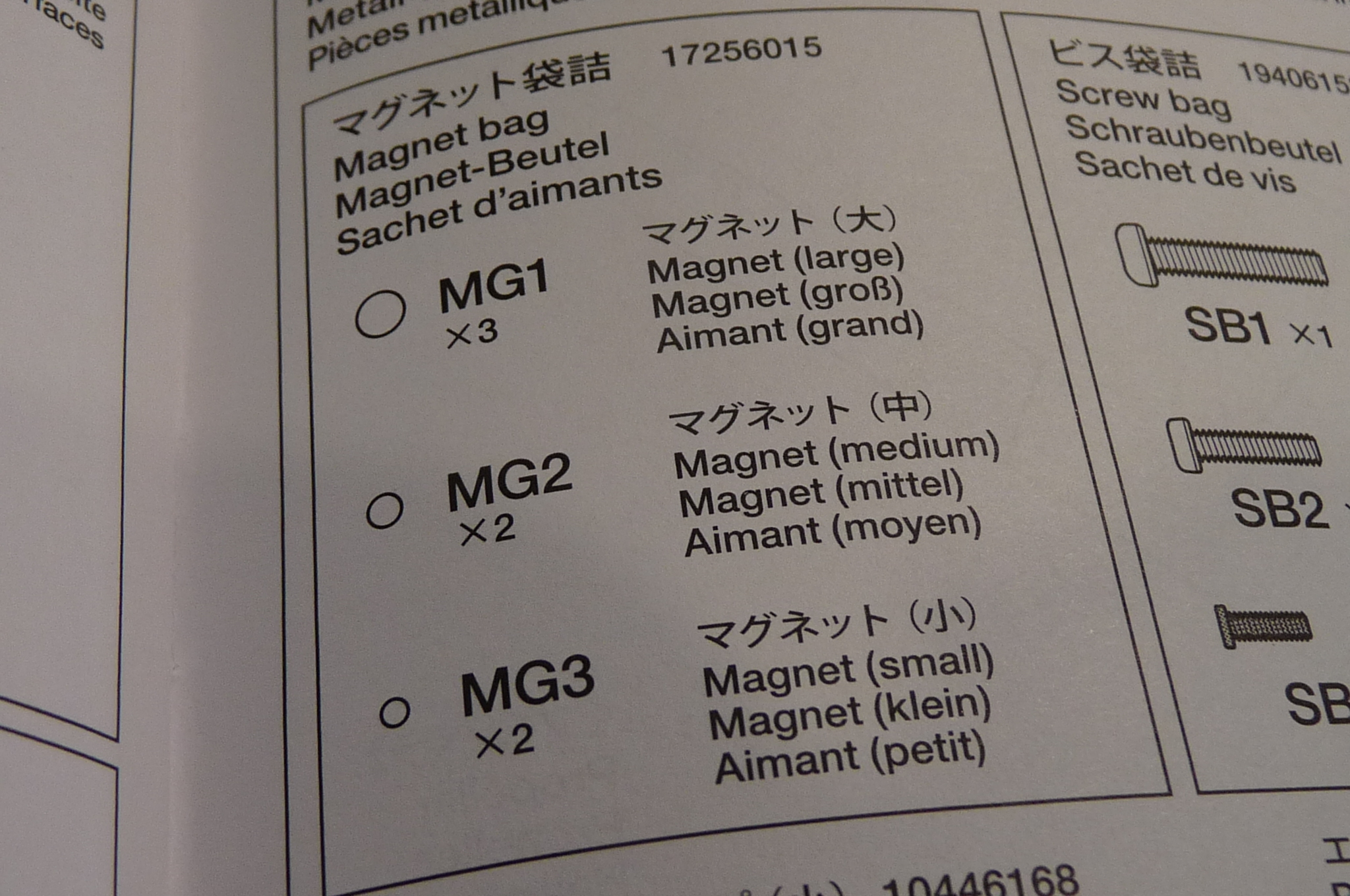
I put the bag with the kit-supplied magnets beside the diagram. Hmm. Which is which? The back of the instructions to the rescue again. MG1 are the three large magnets, so I will next glue one into the remaining Y1 part with CA, then attach onto the assembly in the instructions.
Having learned a small lesson about dry-fitting (for the 10,000th time), I will dry-fit the whole thing in place as per the next step before gluing this time, just to make sure it all orients correctly.
-
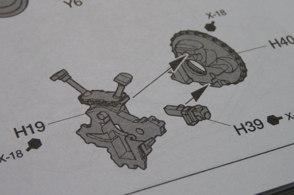
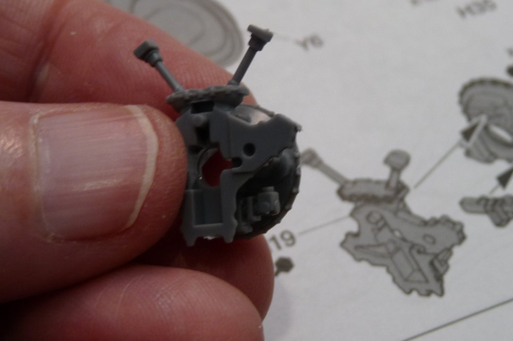
Three little parts come together here. At first, the one with the funny legs sticking up gave me some trouble, because I was fitting it in place backward. I was trying to fit the side of that part that is facing out of the page in the instructions onto the face of part H40. I tried a few times, but it didn't locate right. Flipping it around, it instantly fit perfectly in place - just like everything else Tamiya engineers.
-
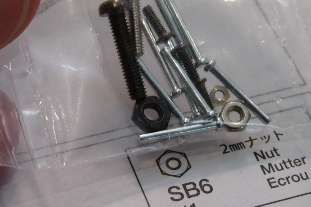
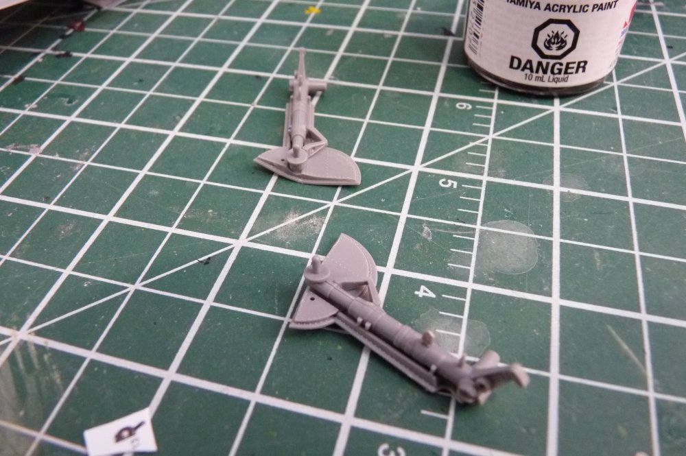
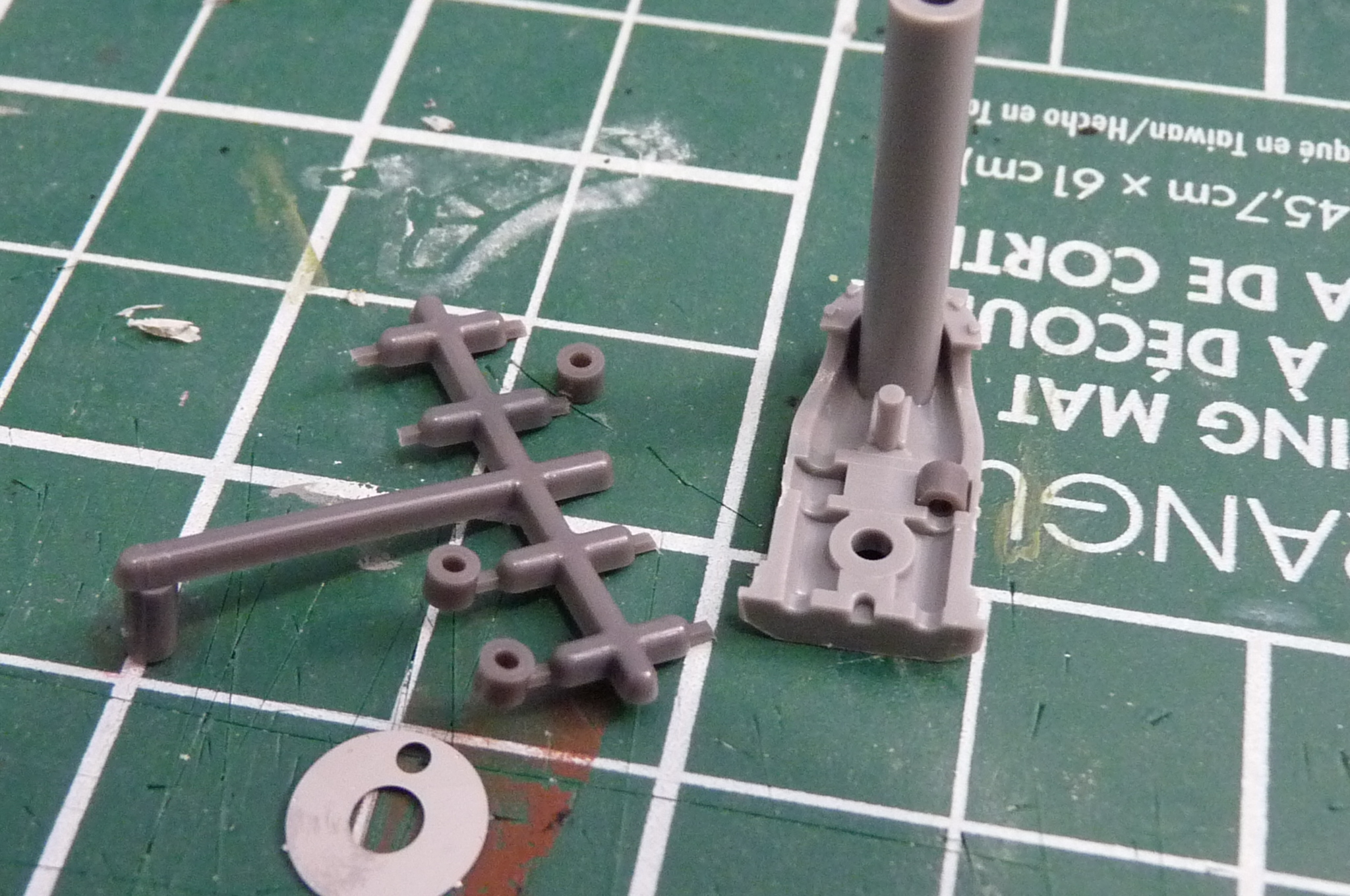
This next part was tricky. Two little silicone tubes slide into depressions in the back part, and a little nut goes into the part that glues on top of it. Easy to figure out which of the silicone parts were intended - the others are significantly larger.
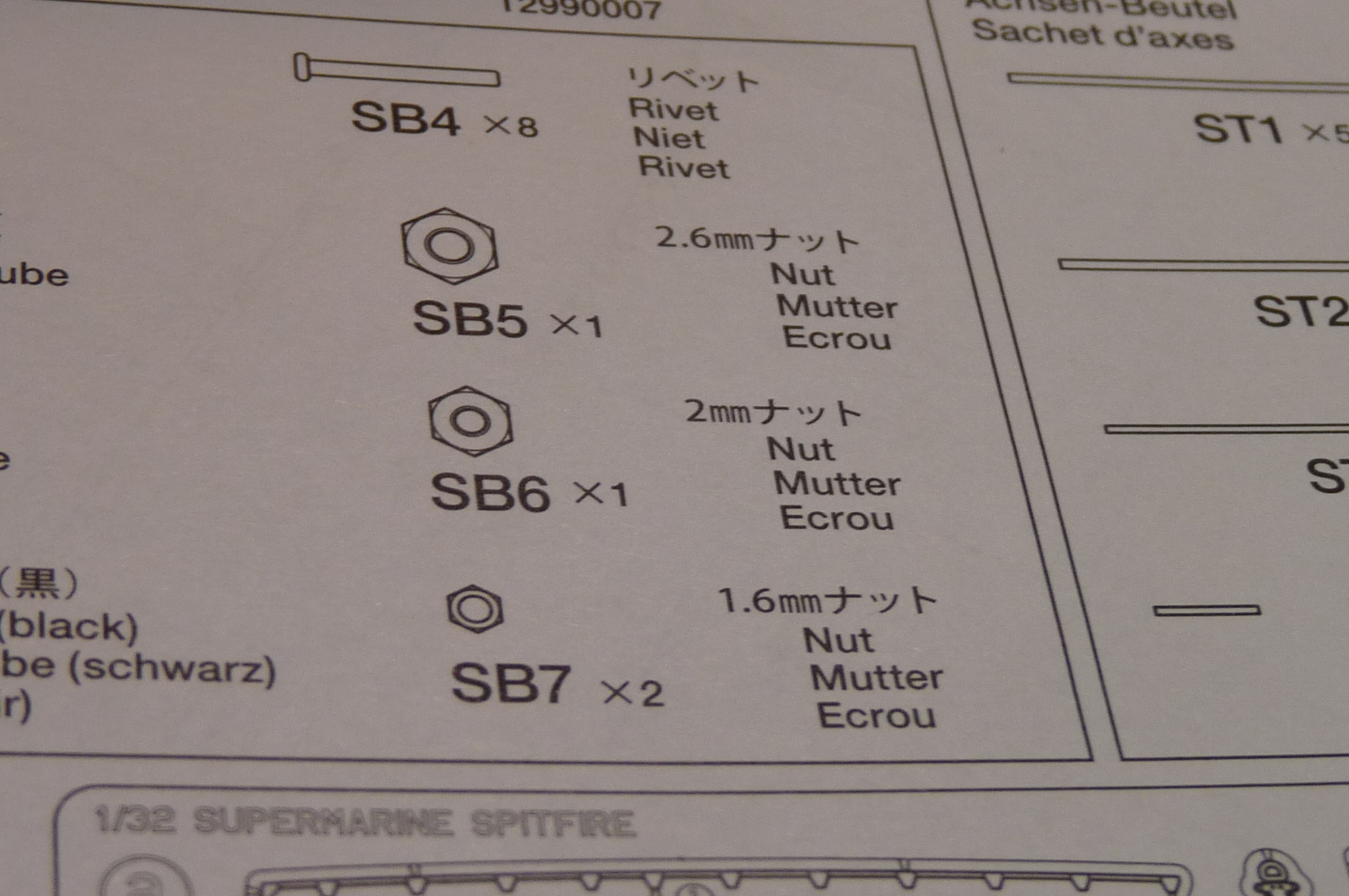
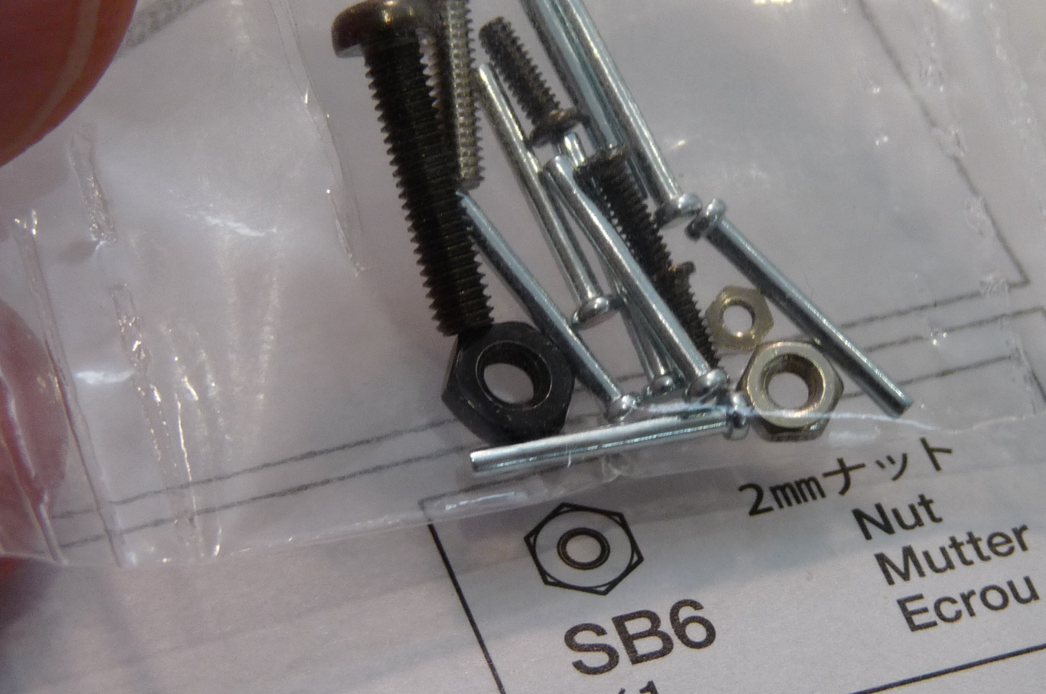
Less obvious was which of the nuts (the larger of the two silver ones, or the black one) was to fit into the other part. Holding them up to the full-scale drawing in the instructions, it was hard to tell while they were still in the bag. I am too afraid of the carpet monster to pull them all out and risk losing them in the process. Flipping toward the back of the instructions, I found that there are three sizes of nut. SB6 is the medium one, so the larger silver one it is!
I then had a bit of trouble with the gluing of the two parts (the one with the silicone, and the one with the nut) together. The instructions say no glue on the silicone, so they just fit in place. When I picked up the part with the silicone tubes, I managed to drop one, but luckily the music wasn't too loud and I heard it drop. Found it. Phew.
I then left the silicone one on its back so they wouldn't fall out, and quickly flipped/clicked the nut equipped part into place. In hindsight, I should have used a dab of CA glue to hold the nut in place, then I wouldn't have had any trouble at all with this step. I'll know next time.
Still a mystery to me what the nut and silicone tubes are for, but blindly following directions.


-
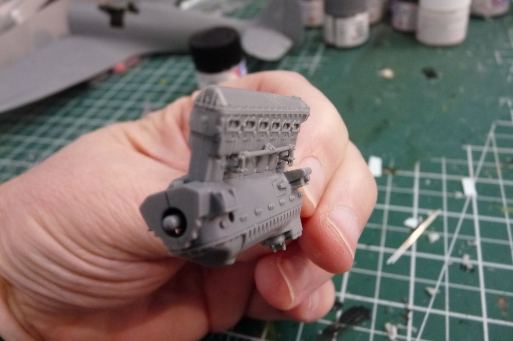
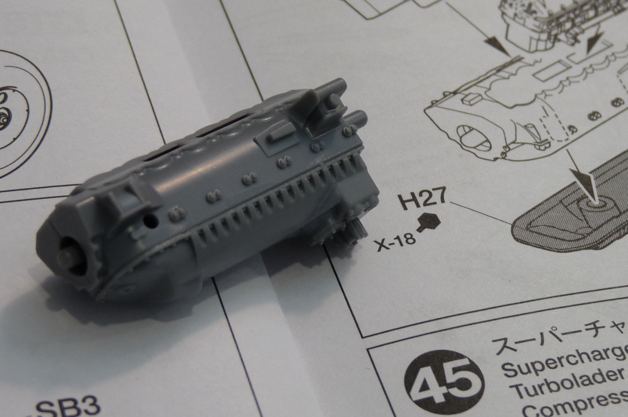
One fun thing about the engine is it also teaches me how the big V-12 works. Note how well the row of six cylinders fits onto the crankcase here. The moulded detail is incredible, and the parts fit beautifully together. Given that these parts would be largely painted black, that little seam will be invisible.
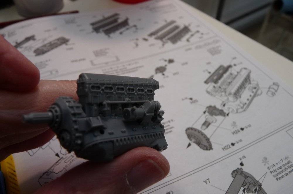
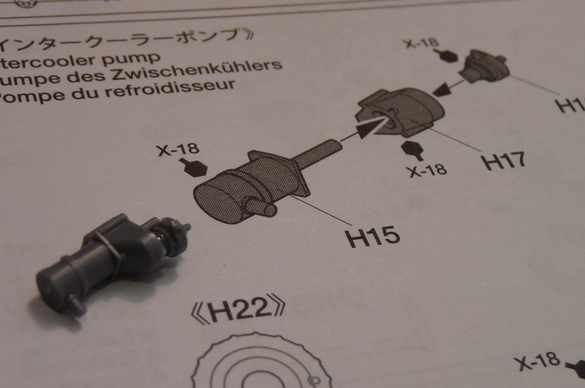
The intercooler pump is tiny, but made of three parts. Careful study of the drawings is necessary to make sure things go together in the correct orientation.
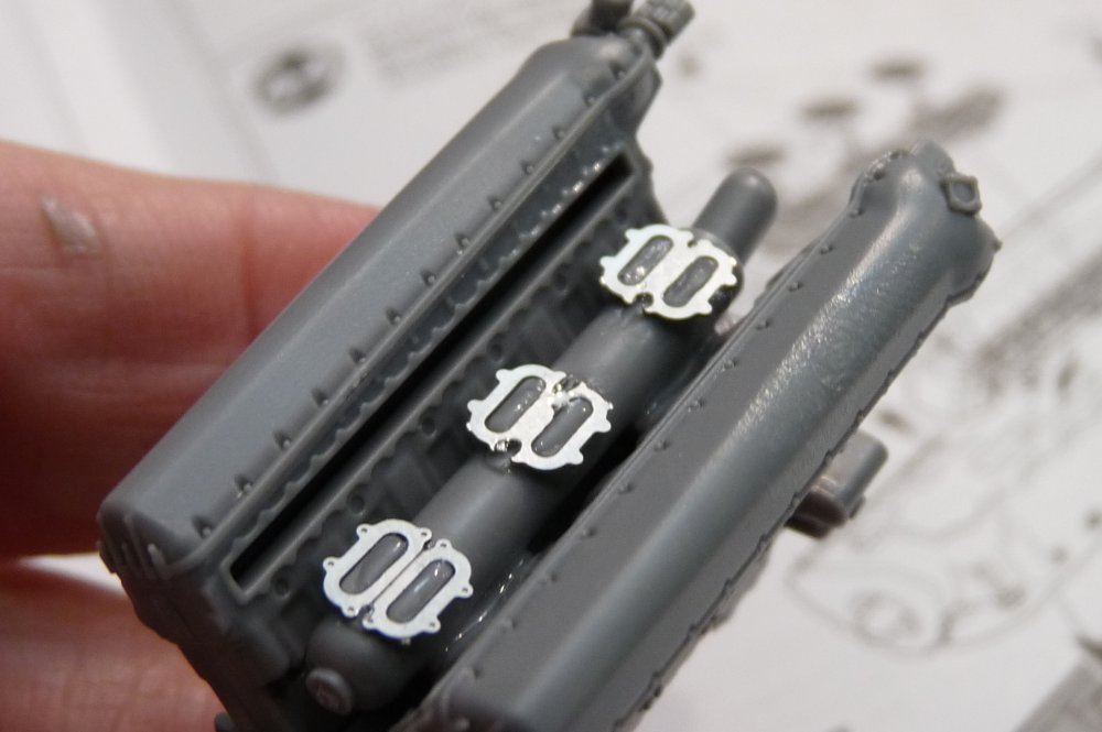
There are some PE parts here - CA glue does the job. In the pics, I can see that the PE has an upper and lower side (with and without the little indents). Hard to tell from the instructions which is correct, so maybe it's a good idea to check which side is up on the PE (sprue? what's the PE holder called?) before you chop them out. This will be buried in the engine, so not too obvious a factor.
The intercooler fits nicely onto the left side of the engine block. Again, careful study of the instructions is needed to make sure it sits right.
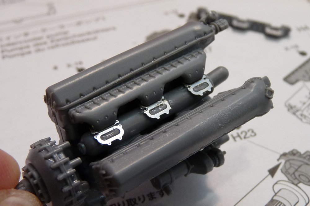
I did some dry-fitting on the top two parts before adding glue. The three parts sticking out from the manifold fit nicely on top of where the PE is attached.

-
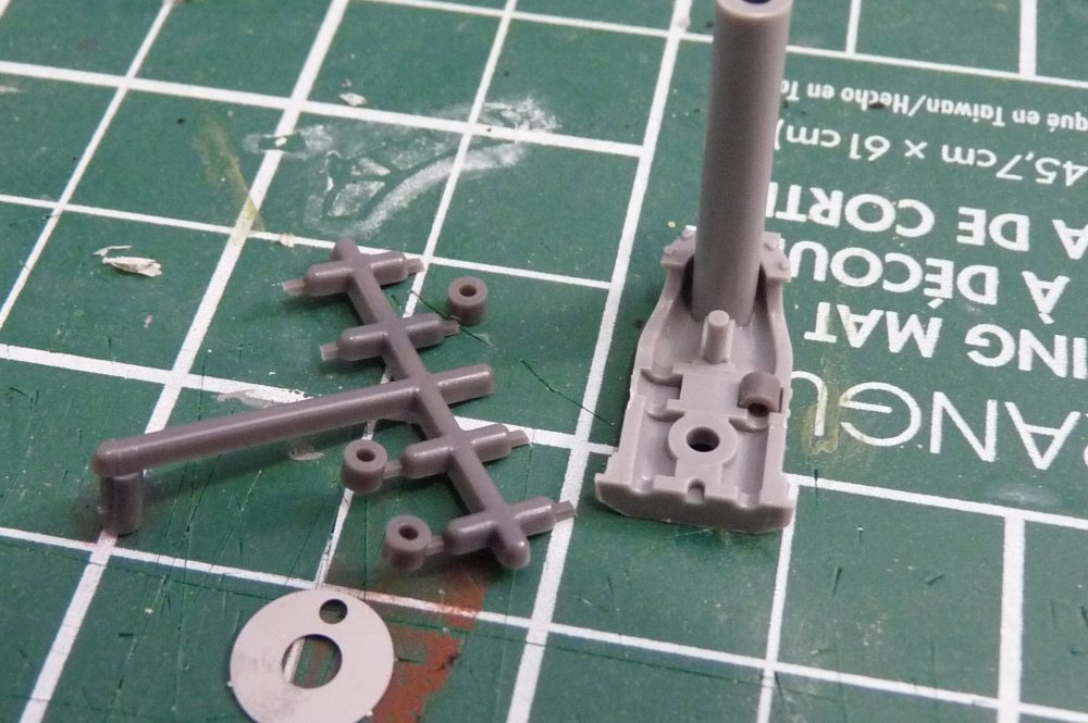
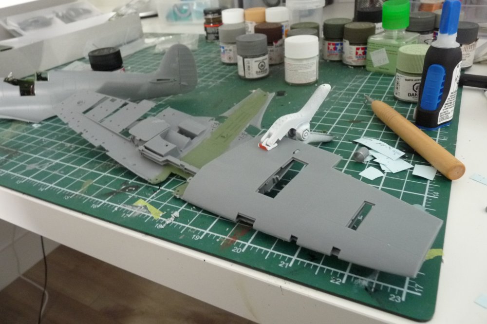
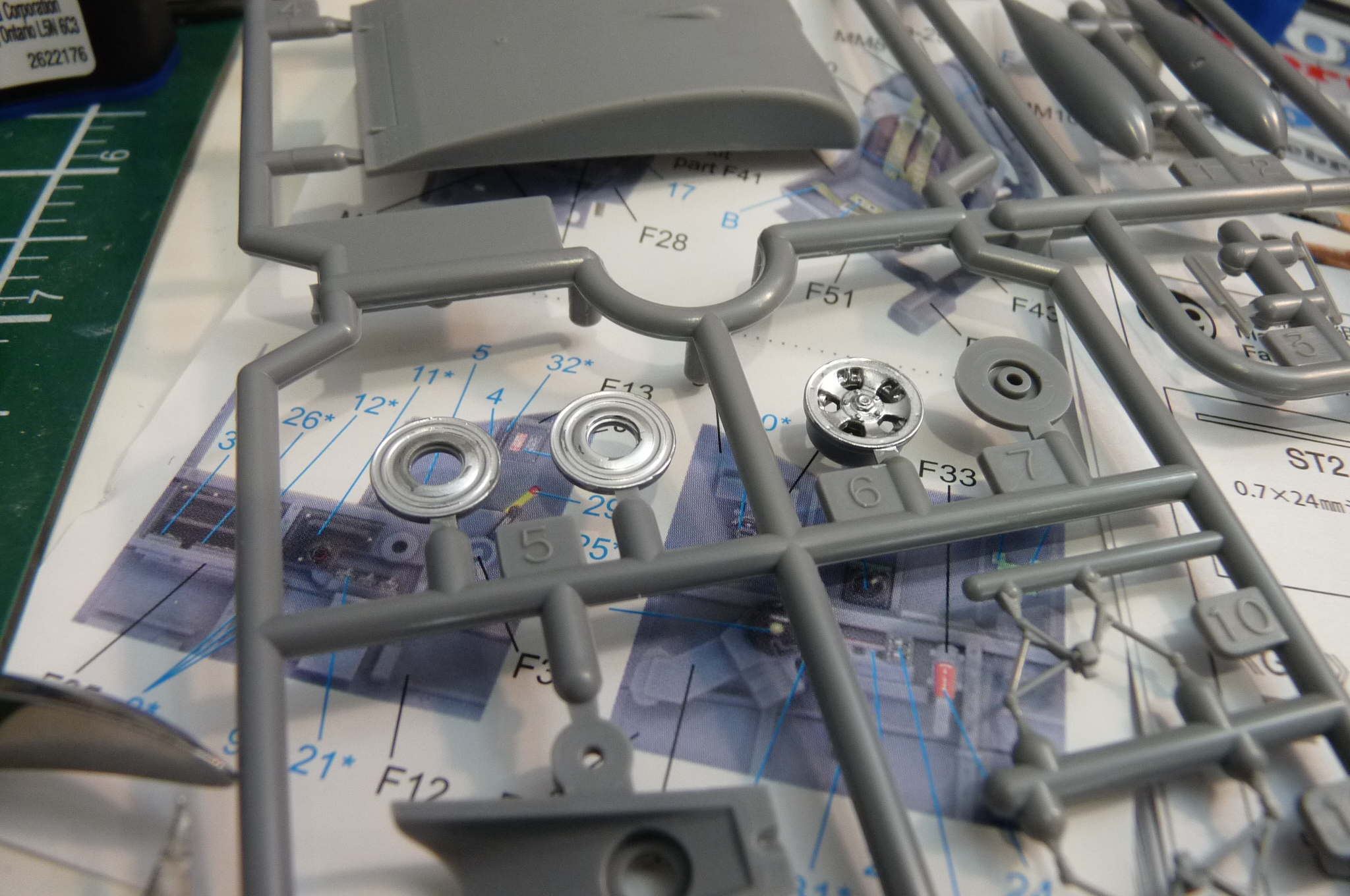
In parallel to the engine, I built up the main landing gear legs and their doors. What's easy is that the colour is 'underside,' meaning I can paint everything at once on these. The oleos are silver, so I'll use my silver pen to add that detail after the big bits are painted. All these parts go together beautifully.
I've also prepped the wheel parts. I'll be using the rubber tires (or should I say tyres, given it's a British aircraft?). So confusing. 🤥
You can see the glossy silver from my pen on some of the parts. Still have to figure out exactly how the PE parts fit into the whole thing.

-
Thanks, Barkin Mad, for your confirmation of the flaps and radiator configurations. Easier to build this way as well. 😏
Progress has been in fits and starts, due partly to the fact I've been teaching online Aviation English and Supersonic/Transsonic Theory of Flight courses at the Aviation College I taught at full time until five years ago. Due to the shortage of pilots in the industry, they finally bent on the 'never online' approach they had, and I'm able to do classes from home. While it's good money, and fun to once again interact with enthusiastic professional pilot trainees, it has been cutting into my modelling time.
The other factor is the sheer complexity of this kit. The engineering is superb, and the detail for the scale just blows me away. I've started on the engine. OMG, what a complex beast! The guy I'm building it for doesn't intend to have the engine displayable, but I will build this one up for two reasons.
1. I don't know how much of the engine and its mounts are necessary to attach the front fuselage panels and the prop, and
2. I am fascinated by the complexity and thinking of making my own engine displayable. It looks like the side panels can be held on by magnets which are supplied with the kit, so I want to see how much painting needs to be done, and how well the magnets hold the panels in place.
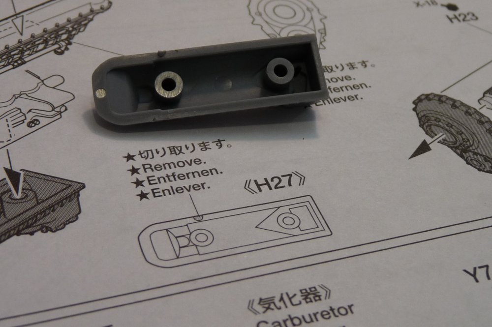
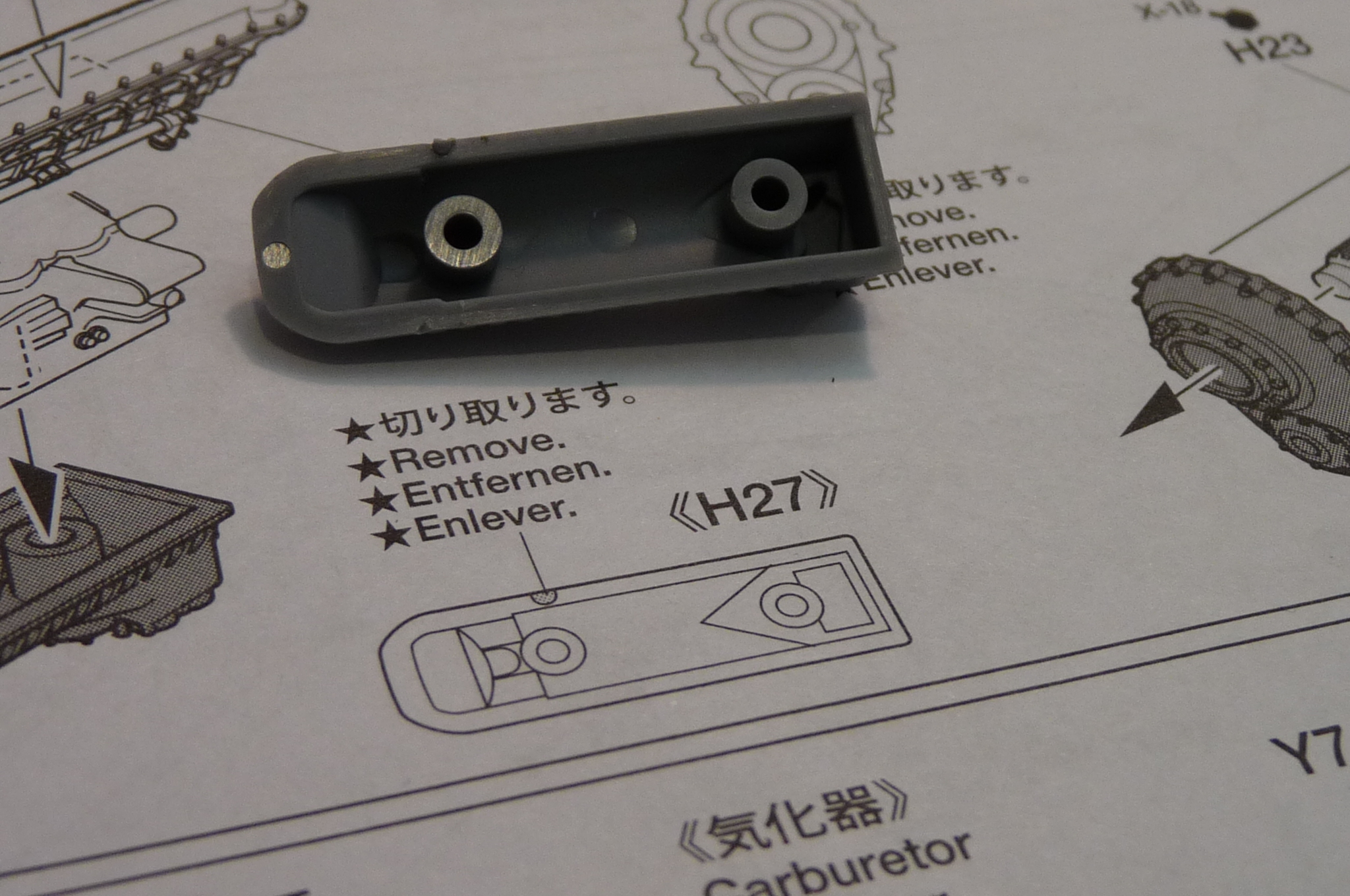
One thing to pay close attention to in the instructions is where it says to remove little bits of plastic. In this case, it appears that the moulding goes over onto the top of the part, and those extra bits of plastic need to go. If they're not chopped, the seal in the second picture is not as perfect as it is here.

-
On 3/14/2024 at 9:50 PM, KursadA said:
Not really - you have used the correct ejection seat. By the time the CF-104s were repainted in the Turkish camouflage scheme in the early 1990s, all of the fleet had already been equipped with the MB seats that were removed from the F-104Gs that were retired earlier. There were no Turkish CF-104s still flying with the Lockheed seat after approx. 1992 or so. Excellent build!!
Interesting information, Kursada.
Janissary, that is one awesome build. Looks fantastic. As promised in a DM, here is what I found for RHAWR (Canadians called it the radar homing and warning receiver at the time, not RWR). A user here on ARC, called CF-104 of course, made a great version of a CF-104 that will show you how he did it. He knows a lot about the real aircraft, and I learned some stuff from him as well.
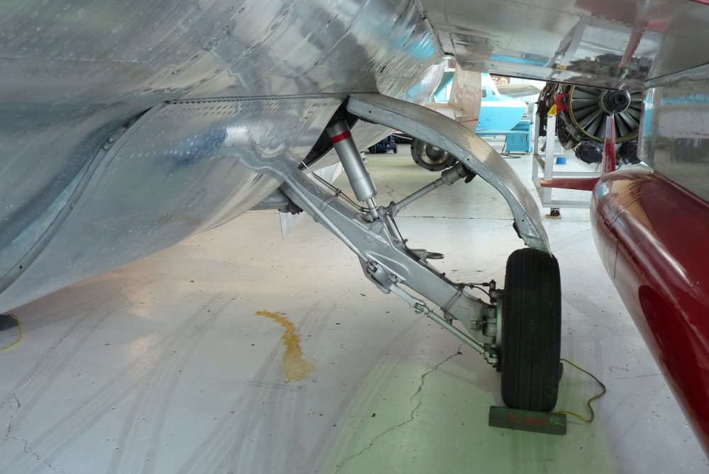
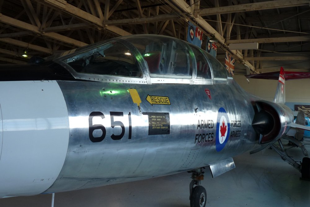
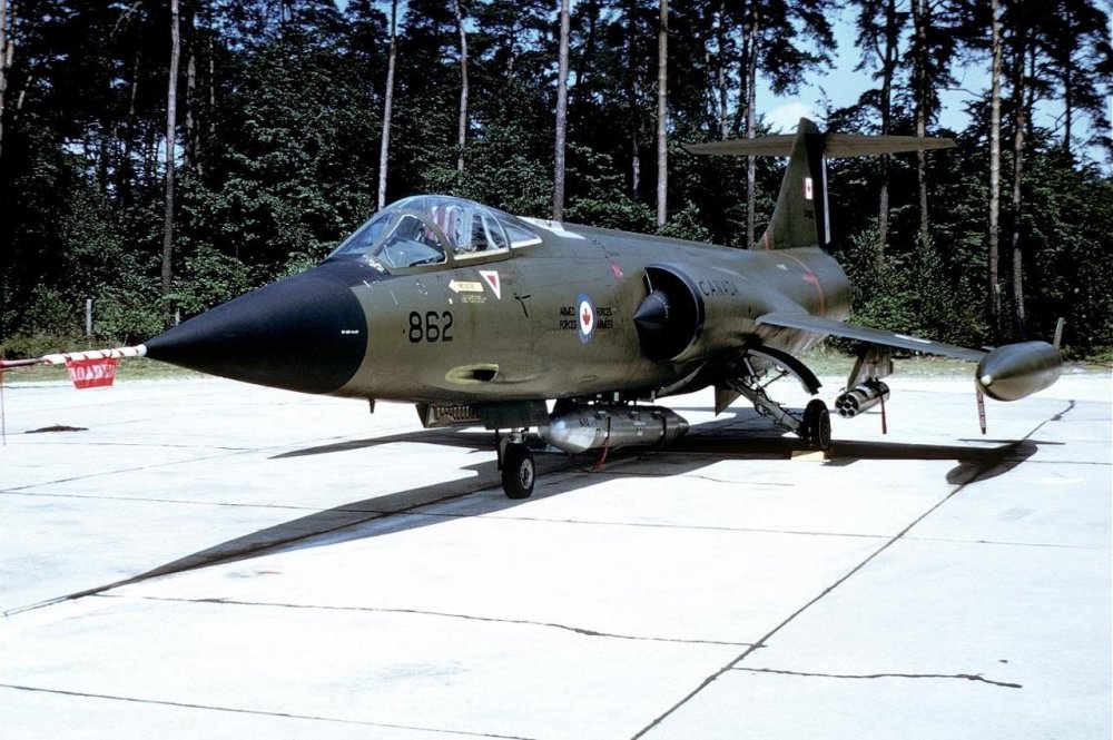
For your interest, I dug up some photos I took in a museum at Edmonton Municipal Airport almost 10 years ago. The Starfighter they have on display is called a CF-104, but it's actually an F-104G that has been painted to look like a Canadian one. You can see that it has the G model bulged gear doors, as well as the IR sensor.
I've also attached some pictures I took of the 'Tiger bird' from the 1976 Tiger Meet at 439 Squadron in Baden-Soellingen. You can make out the RHAWR antennae on the nose and tail, and also the non-bulged main gear doors and the lack of IR sensor in front of the windscreen.
.thumb.jpg.470d95e6bea662015cd319afe4c6de38.jpg)
.thumb.jpg.71b542773681c0f7aad60d8acadf3542.jpg)
-
35 minutes ago, Scooby said:
Your father is your spitting image. Nice images.Thanks, Scooby! Great memories from Baden, back in the day.
ALF
-
So, Bekim... are the 3D prints made out of solid gold? I suspect the prices will be high enough to expect them to be made of gold. 😏
ALF
-
Here's the pod, on a CF-104 that was involved in a Tactical Air Meet in 1974. Illu is correct, the CF-104 doesn't have a suffix, but the tail makes it look like a G. Differences include (CF-104 doesn't have): IR sensor at bottom of windscreen, bulged main gear doors, beefy main landing gear wheels.

-
Super work! I especially love the authentic-looking paint job. 😍🏆
Here's what CF-104s looked like back in 1974, when my father flew them. This aircraft took part in the Tactical Weapons Meet. I was 15 years old, and used to climb under the barbed wire by the control tower in Baden to watch the jets taxi by. The Military Police never caught us, and the pilots all waved at us as they went by. The second picture is at a Tiger Meet, with my father at far right in the photo. Fantastic job, Janissary!

-
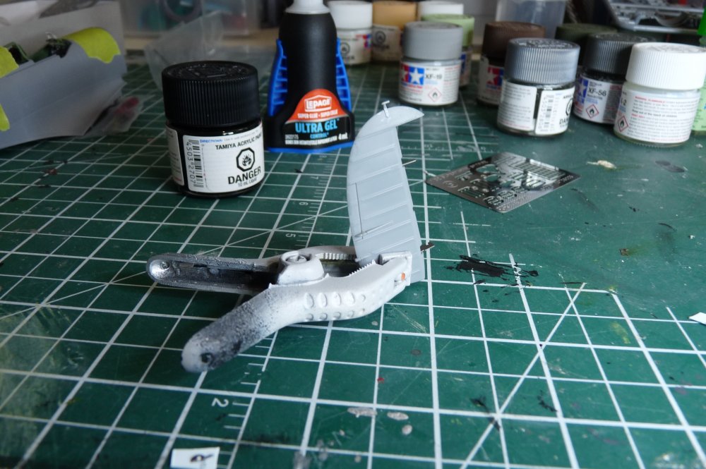
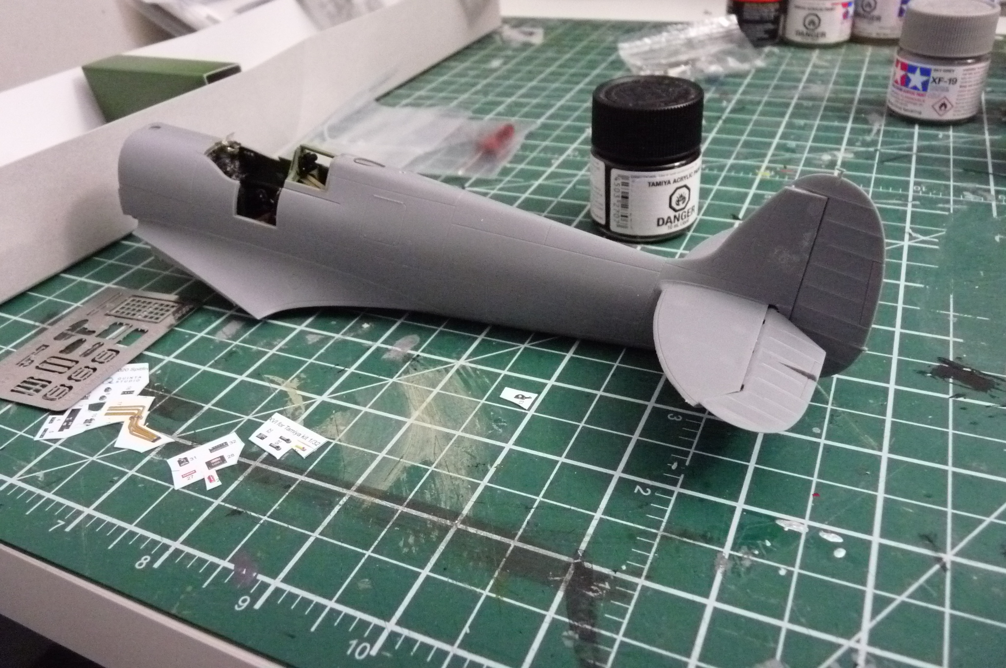
Horizontal stabilizers and elevators installed. Tiny, fiddly parts for the hinges.
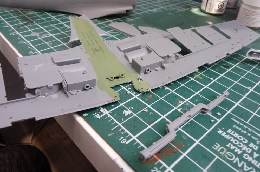
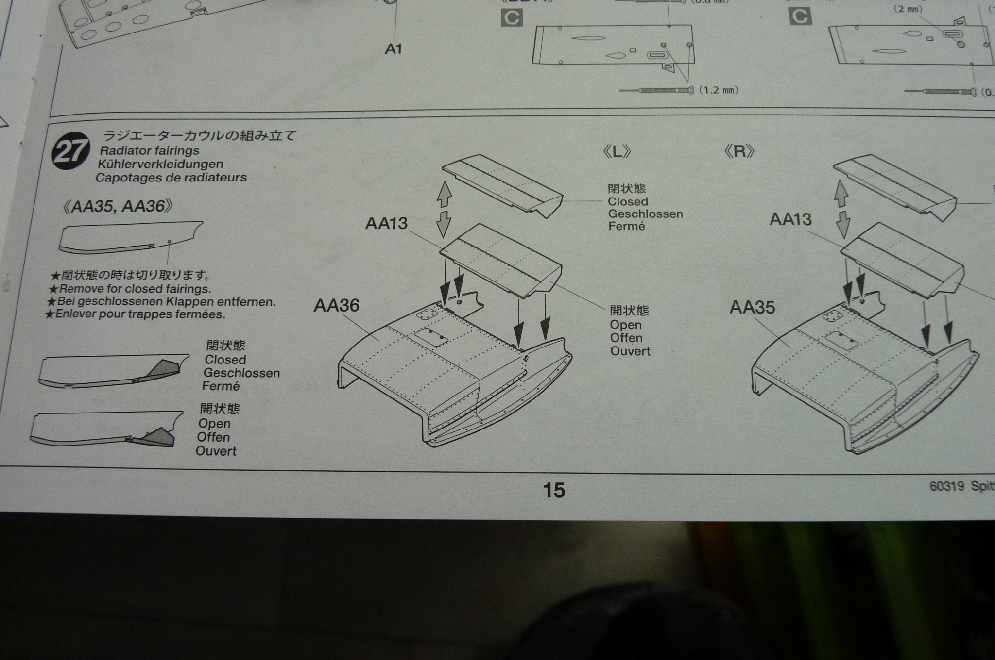
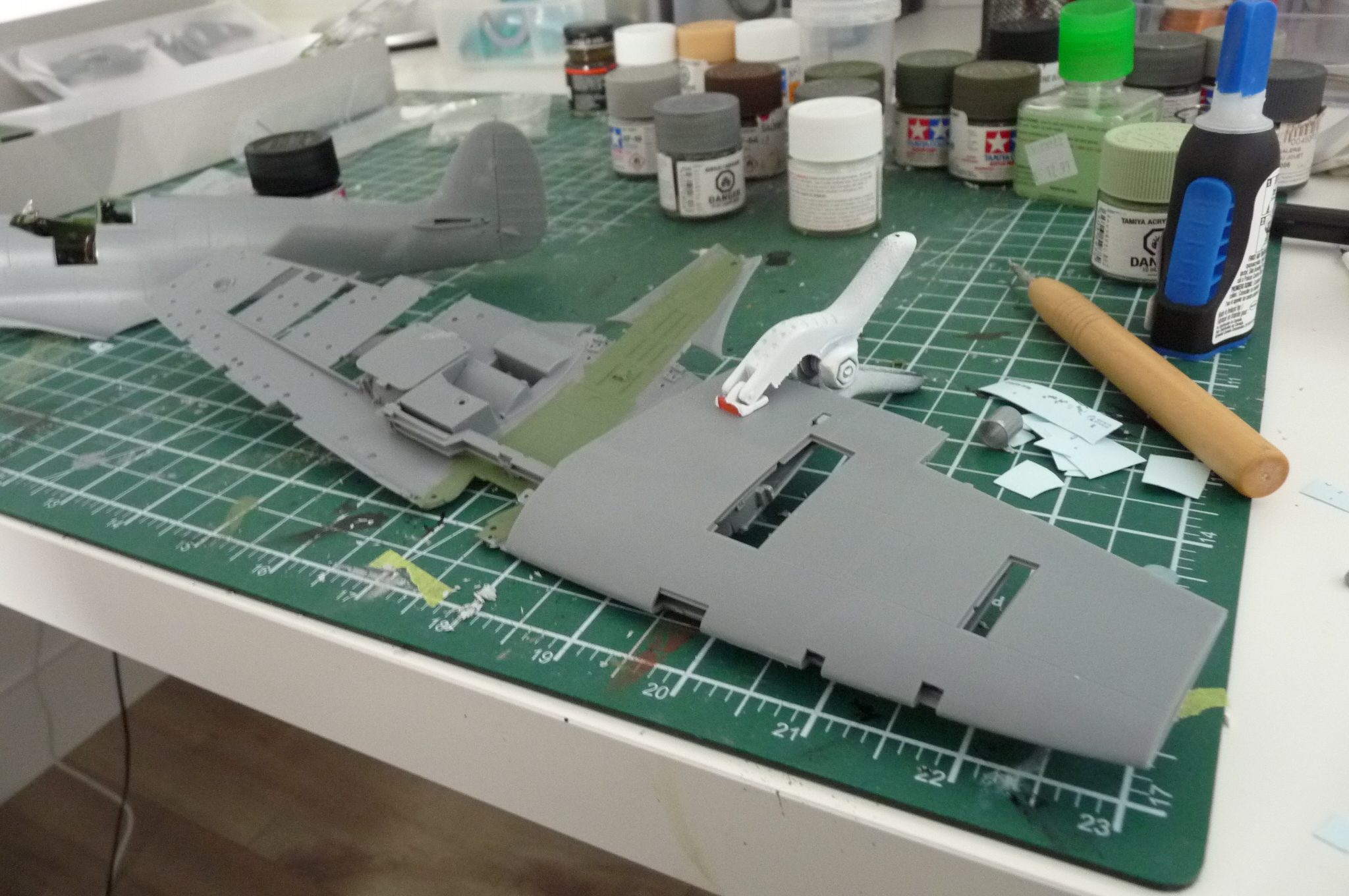
I'm about to work on the radiators. Not sure if they should have open or closed fairings. Anyone know? I plan to have the flaps up, since I've learned from several reliable sources that Spits almost always got parked with flaps up, despite the kit having the flaps down option and lots of after-market stuff is made for this state. Fairings... looking into it.
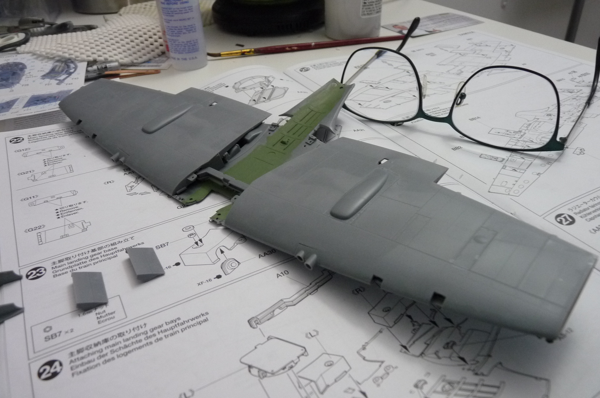
In the meantime, here is the finished upper and lower wing. It all fits very nicely.


-
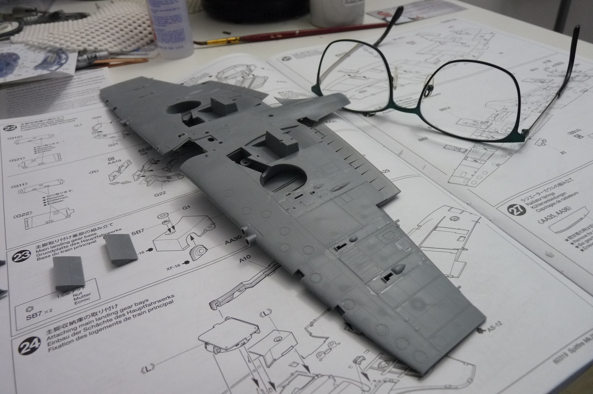
The bays are in place, and the long part along the top also fits perfectly in front of them. Now, the wing halves. They went together nicely as well, with no gaps.
More soon.
ALF
-
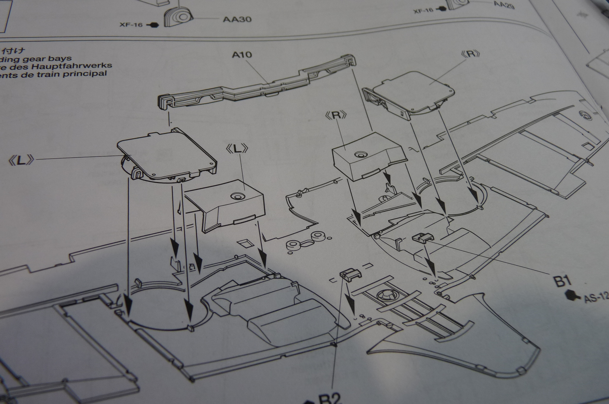
Main landing gear.
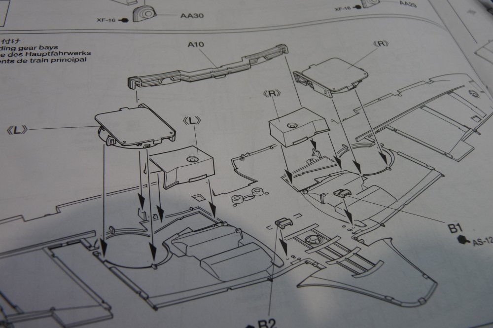
Parts L and R (the outer parts of the MLG bays) have about 6 parts each, which took a while to put together. Again, all fit nicely into place. The other L and R, the parts that cover the MLG struts, were interesting in themselves.
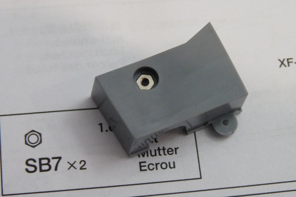
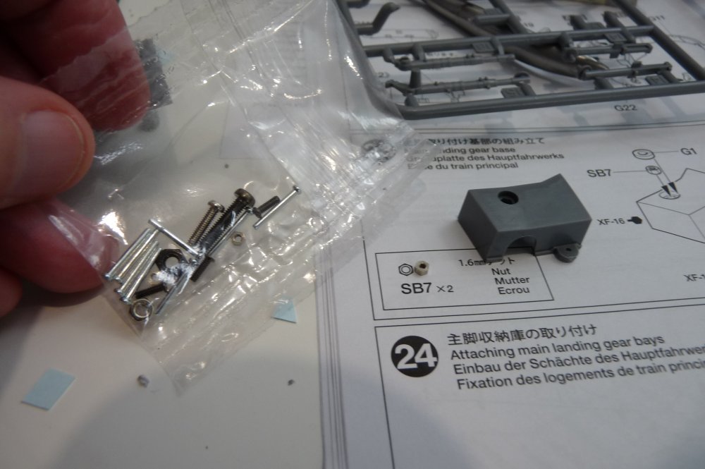
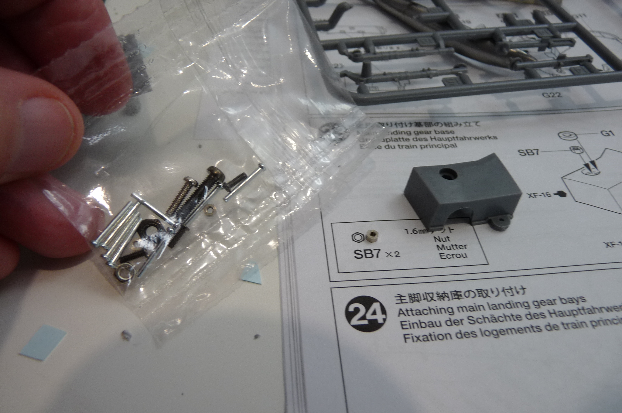
There is reference to SB7, a 1.6 mm nut. Again, flipping to the back, I found drawings and references to the parts. Nuts and bolts are in a little plastic bag. There are four total nuts, one each 2.6 and 2 mm, and two 1.6 mm ones. I carefully fished out the tiniest ones, and saw that it fits the full-size drawing in this step of the instructions. More Tamiya attention to detail, that just demands that the modeller be paying attention.
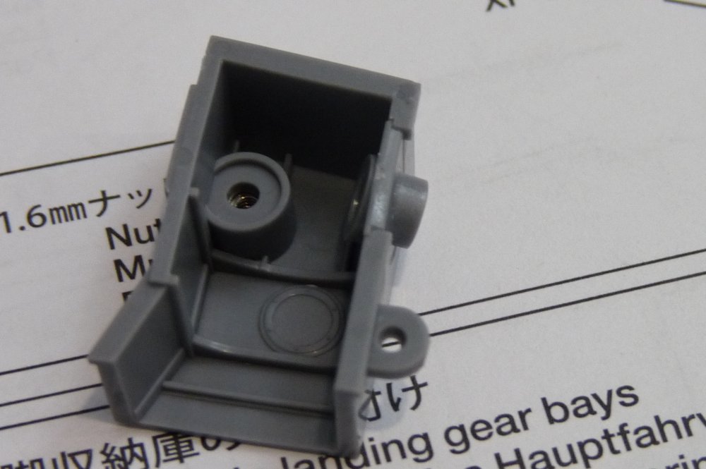
The little bolt fits perfectly into the part - that's as long as the carpet monster doesn't swallow it up. Tiny part. Hard to manipulate. I then glued in the little plastic round retainer on top.
The final piece, that goes into the curved alcove opposite where the bolt goes, was not 100% clearly shown which way it went on the instructions. I looked carefully, and saw a slight curve on the side wall, as well as some very fine ridges on the part. This is how it goes into place. Mirror image for the other, of course.
-
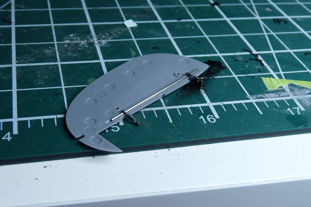
The rudder put together. Also, it's important to use the right one. This Mk IXc has the rounded top rudder, while the kit also includes pointier tips for the Mk XVI. The little call-outs A,B, C are not easy to pick out all the time, but they clearly distinguish which Mark has which part. The fit was superb, of course.
-
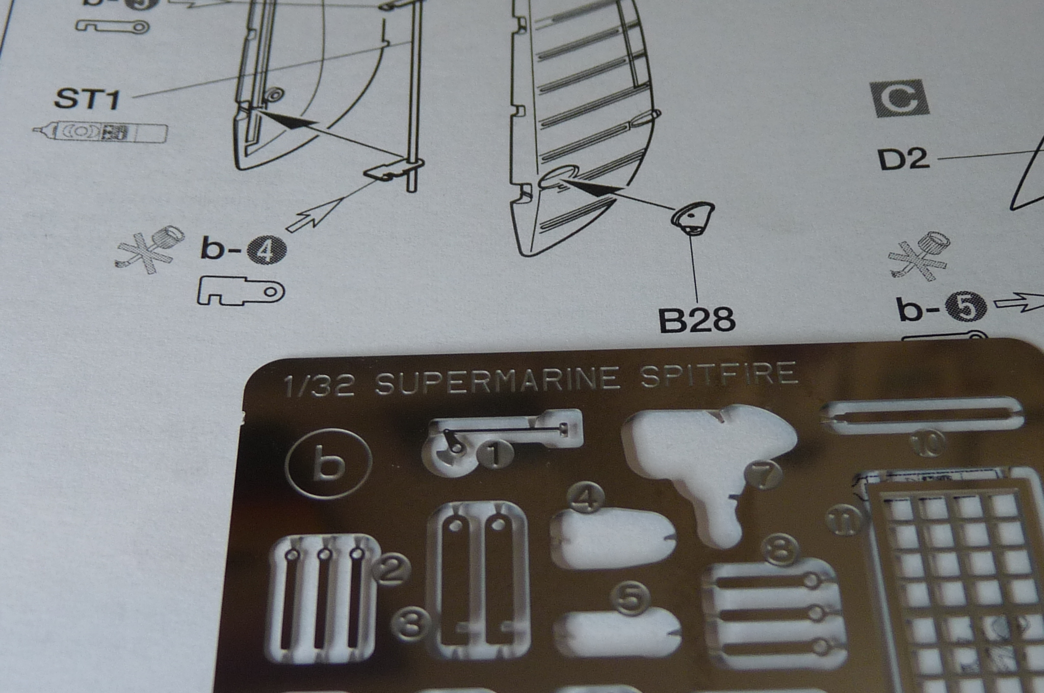
Now onto the rudder, elevators, and wings. The rudder is moveable, with some PE and metal parts. There's a rod that goes between the plastic rudder halves (part ST1). It has two little PE hinges, b-4 and b-5, that are to be inserted onto the rod but not glued in place. Interesting that the 'do not glue' icon is a Tamiya Extra Thin glue applicator, while PE would need CA glue... but I understand why. The part I had a difficult time with at first was the distinction between lower case b and upper case B. The lower case, as you can see on the PE at bottom in this pic, is for b-4, b-5, etc. The upper case B is for a plastic part (B28 on this picture). ST1 was nowhere to be found... until I turned to the back of the instructions where there's a page that shows all the little bits like nuts and bolts, rods, etc, and has drawings and descriptions. Talk about detail!

-
15 hours ago, Mr.Happy said:
Very nice work!
‘Mr. Happy
Thanks, Mr. Happy!
1 hour ago, barkin mad said:Sadly, I can't take the credit for this. Just a useful ref pic I use.
---------------
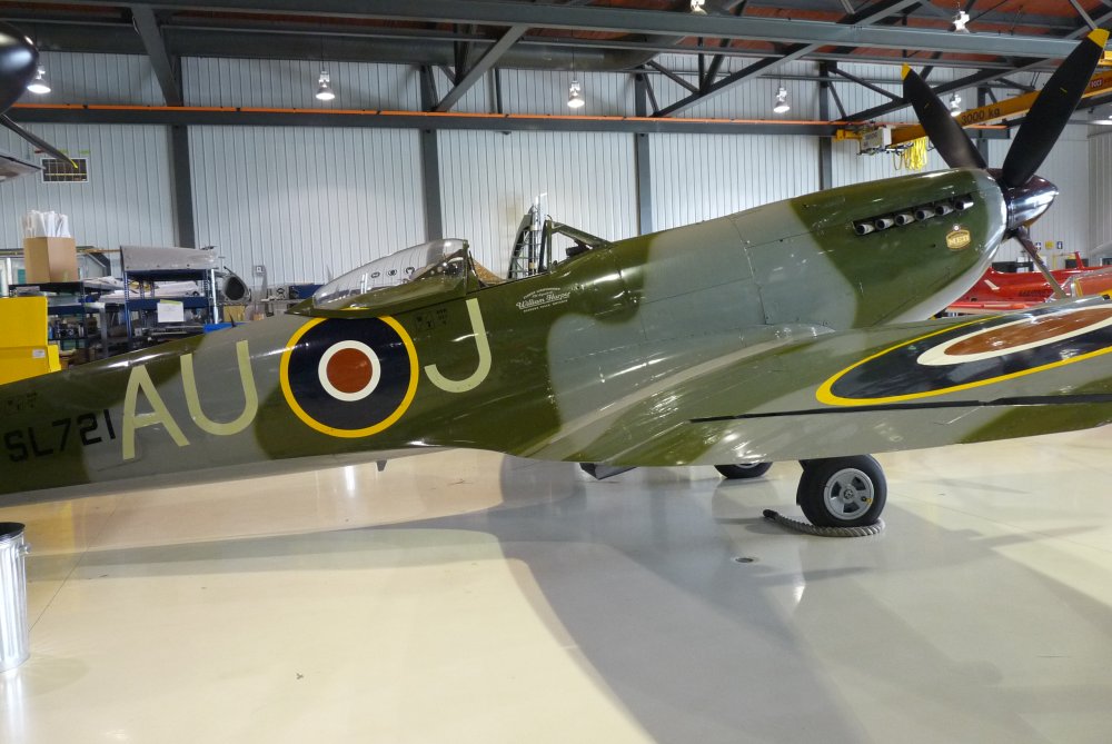
Not a 'mad' (crazy) thing to do, using such a pic. I'm not surprised just how many ref pics exist for Spitfires out there. I've always been fascinated by these aircraft, and I'll never forget the first time I saw one in person, flying. It showed up in May 1973 for the Squadron Colours presentation by Prince Phillip to our three Canadian CF-104 squadrons in Baden-Soellingen. The Spit was part of the airshow, and I got to walk around it and touch everything after the show, accompanied by my 104-pilot father. Years later, I got to sit in a Hurricane cockpit in the flying museum at Gatineau, Quebec, and also the Spitfire they had. I was still very much more impressed by the Spit, but sitting in the Hurricane I couldn't help but be amazed at how the majority of the Battle of Britain pilots had to use that beast to fend off the Nazi hordes. Poor visibility. Cramped cockpit. Not at all like the CF-18s I flew! 🙂
-
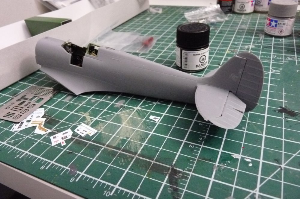
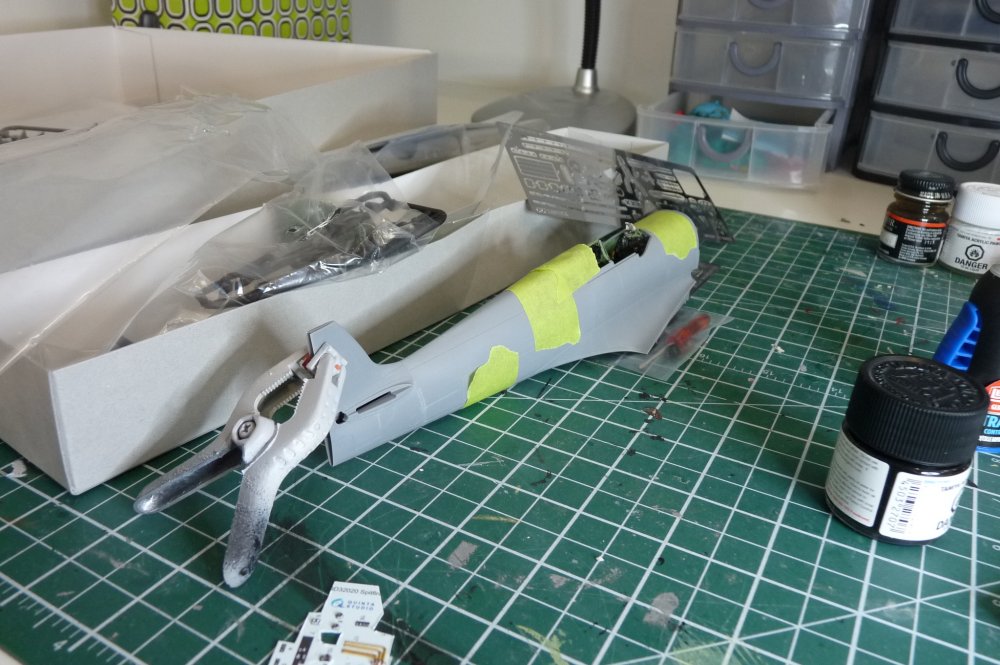
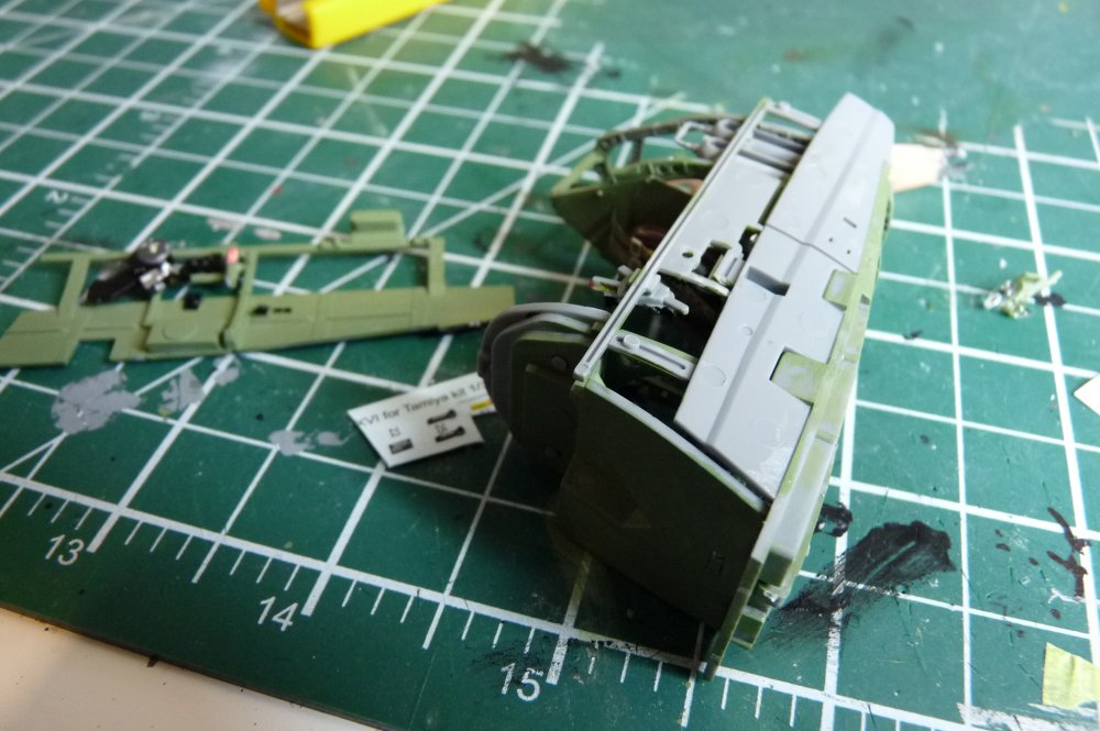
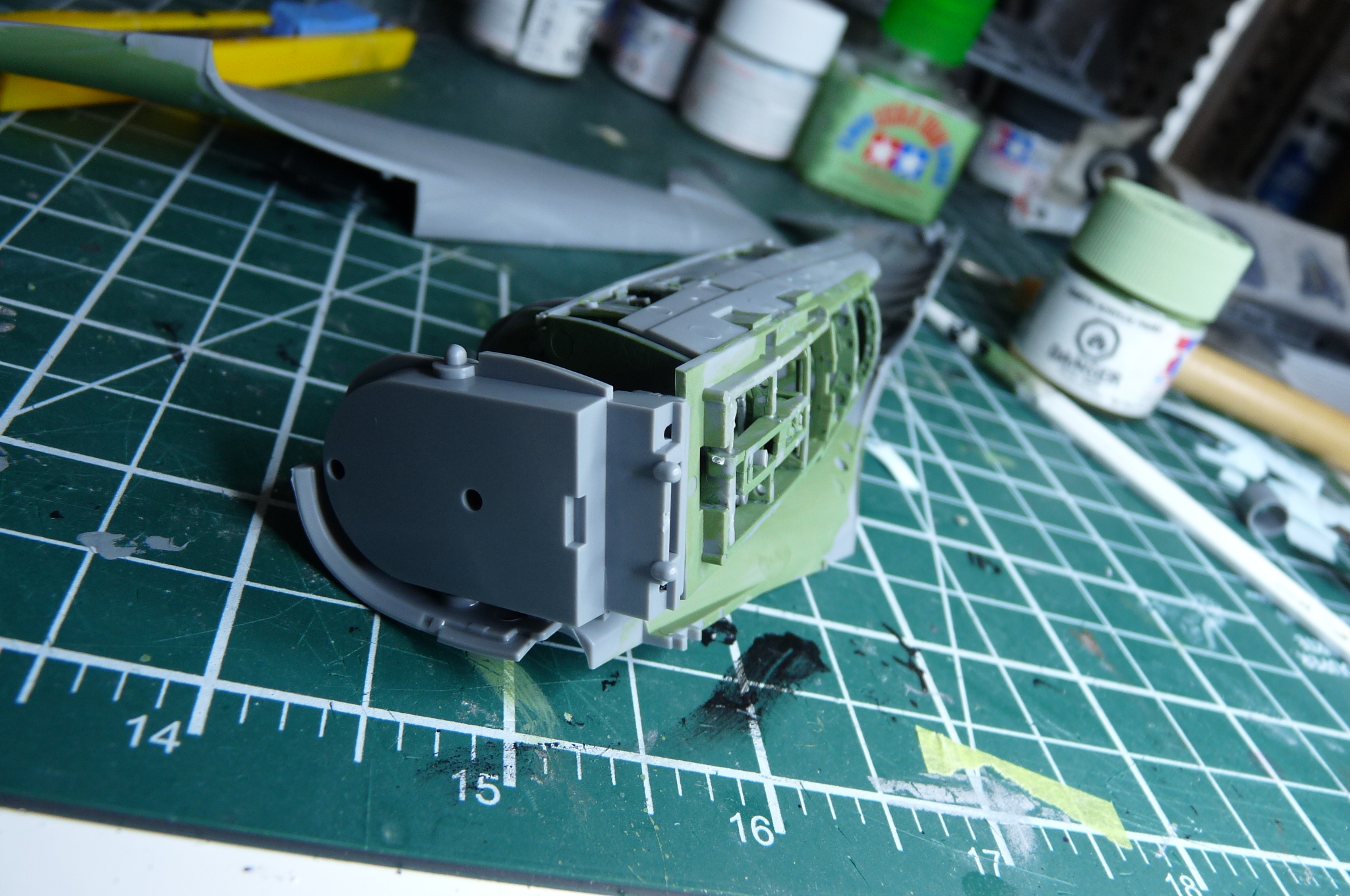
You can see that the side panels fit beautifully with the various cockpit parts. Wonderful Tamiya kit engineering. I buttoned up the fuselage, and set it aside to dry. So far so good. Thanks for stopping by.
ALF


-
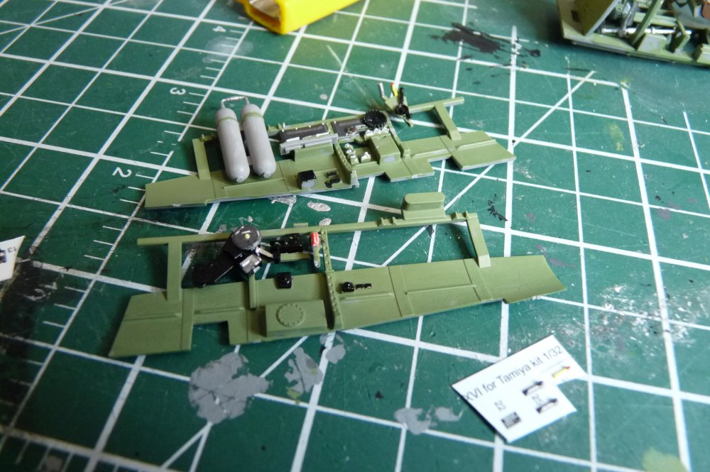
The other bits went into place more quickly. You can see in the kit instructions around where the air tanks go that the Tamiya green area is indeed larger and further forward than the example barkin mad showed above, but I had already buttoned up the fuselage by the time I read his comment. Nice try, something I will take into account during my next Tamiya build (my
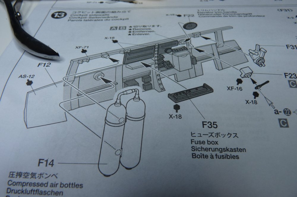 own kit, a Mk XVI).
-

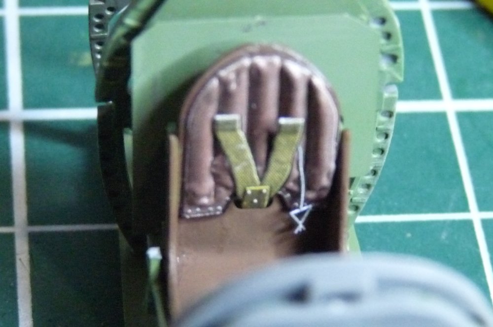
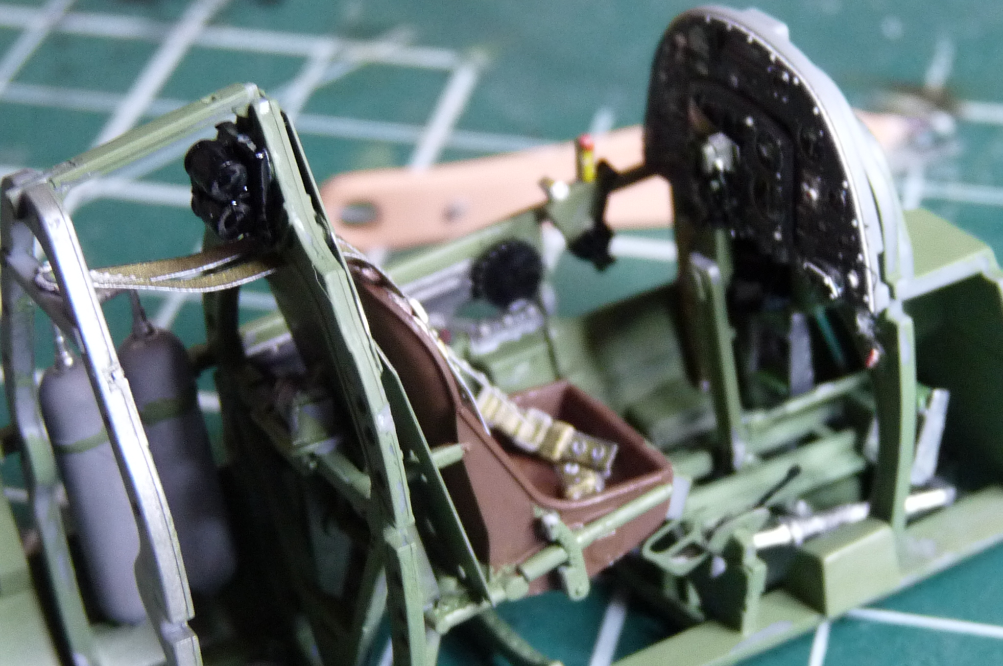
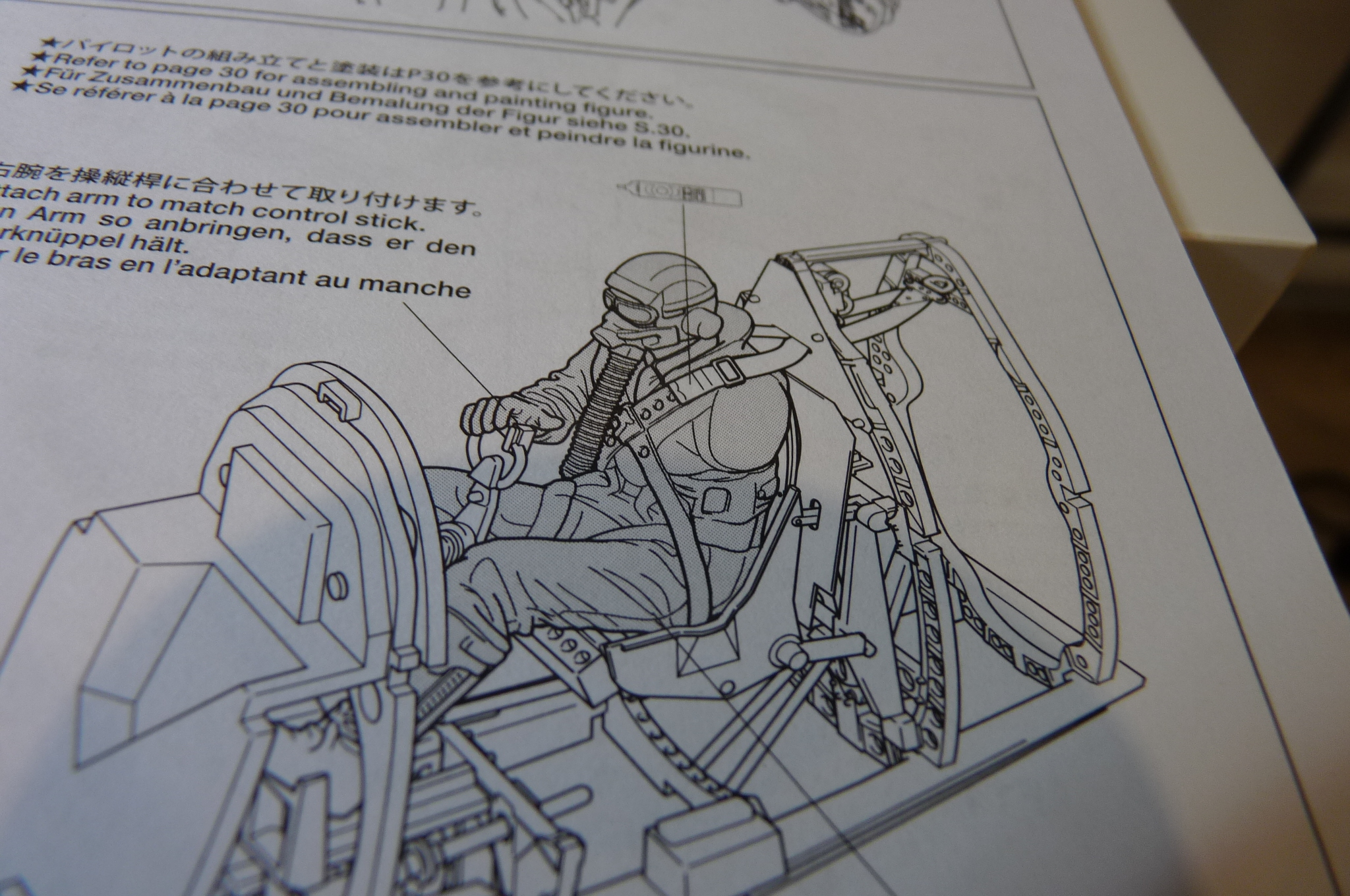
The kit instructions told me what I needed to know about shoulder strap placement, with the anchoring point on the bulkhead well behind the seat.


-
You've done a great job yourself on that cockpit! I did paint some silver on the cockpit sidewall, but not much it would appear. Luckily, that area is hard to see unless you peer inside with a light, once the rear transparency is installed.
Progress is slow, since a lot of this is very meticulous work.
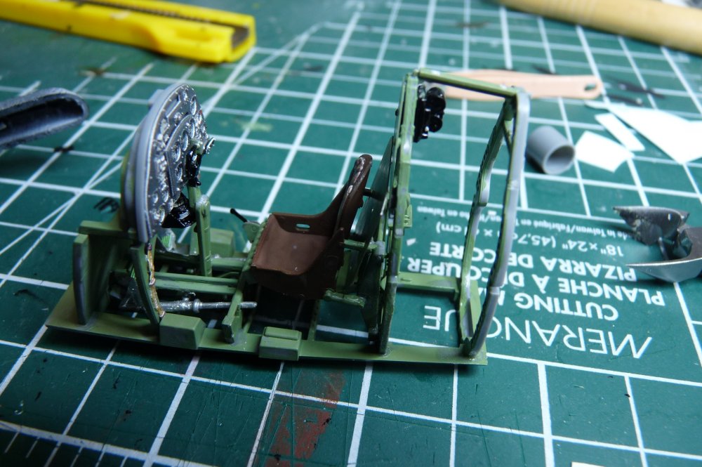
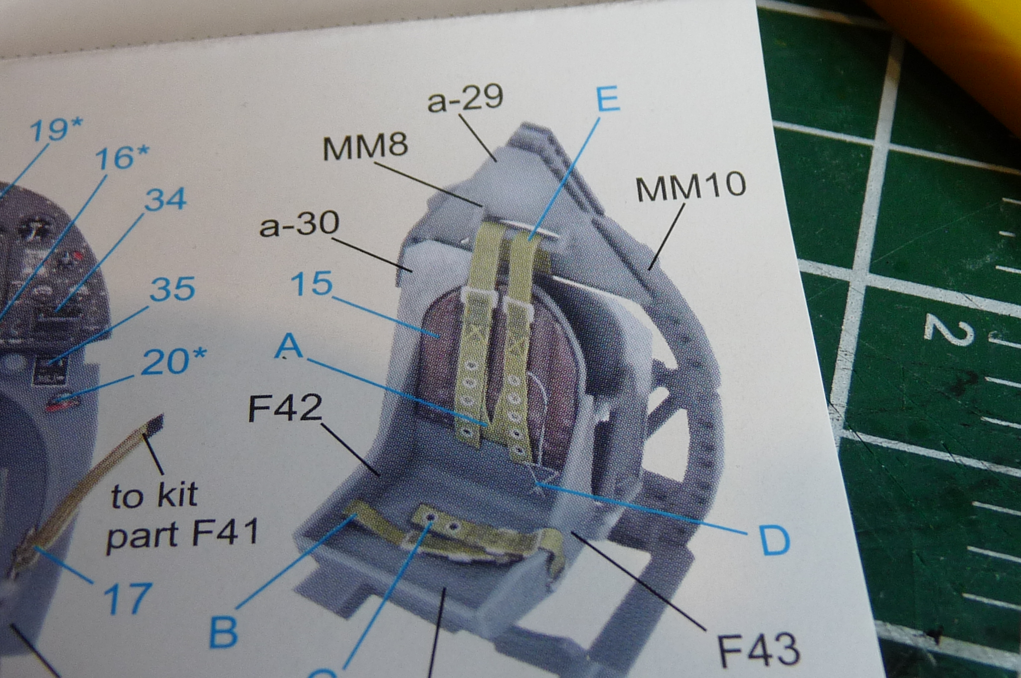
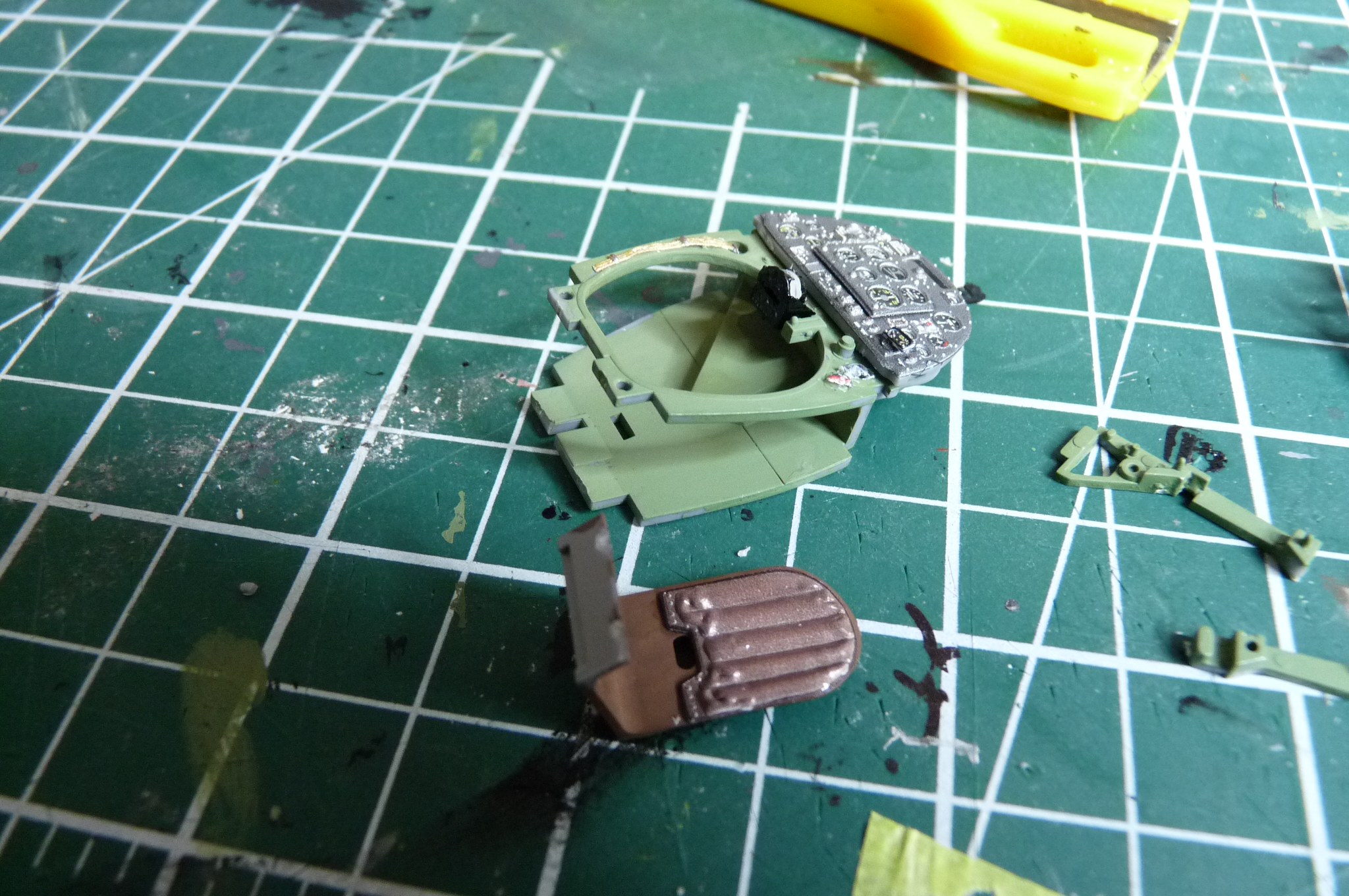
I got the compass installed, and put the panel and other parts in place on the lower frame. Notice the lovely Quinta details on the rudder pedals. The picture from Quinta instructions showed only part of the story for the shoulder straps, but I was able to get the other straps and the little silver dangly part correct. The frame is not fully painted in the last photo.


-
This is where I am now. Instrument panel looking good. I've also glued on the Quinta decal to the seat back, which is a huge enhancement to the kit detail. I painted the seat using the Tamiya red-brown paint called for, and the colour match with Quinta is not bad at all.
Thanks for looking - more soon.

-
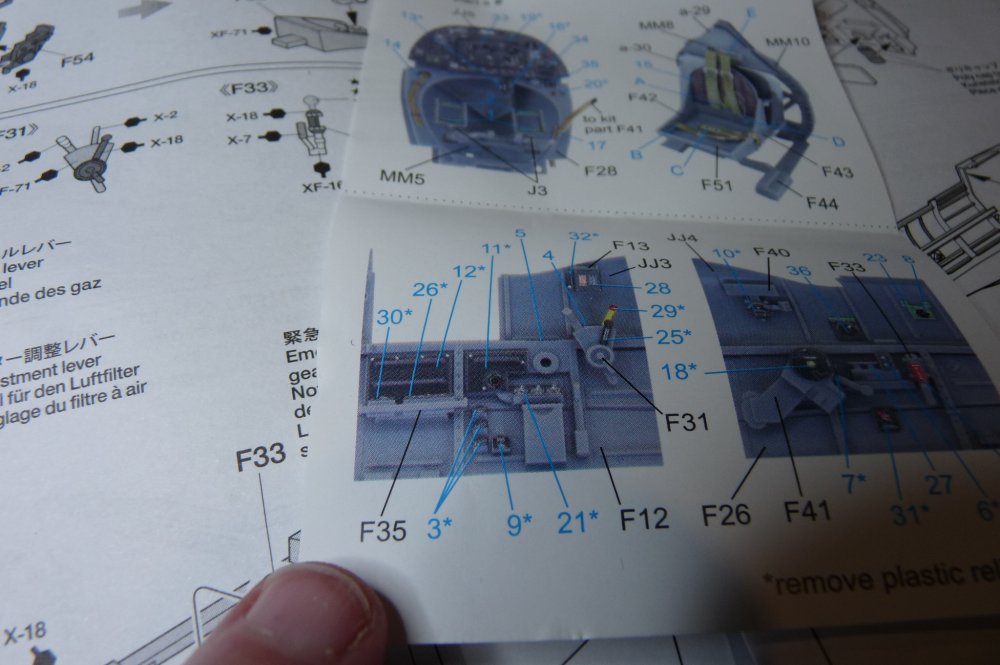
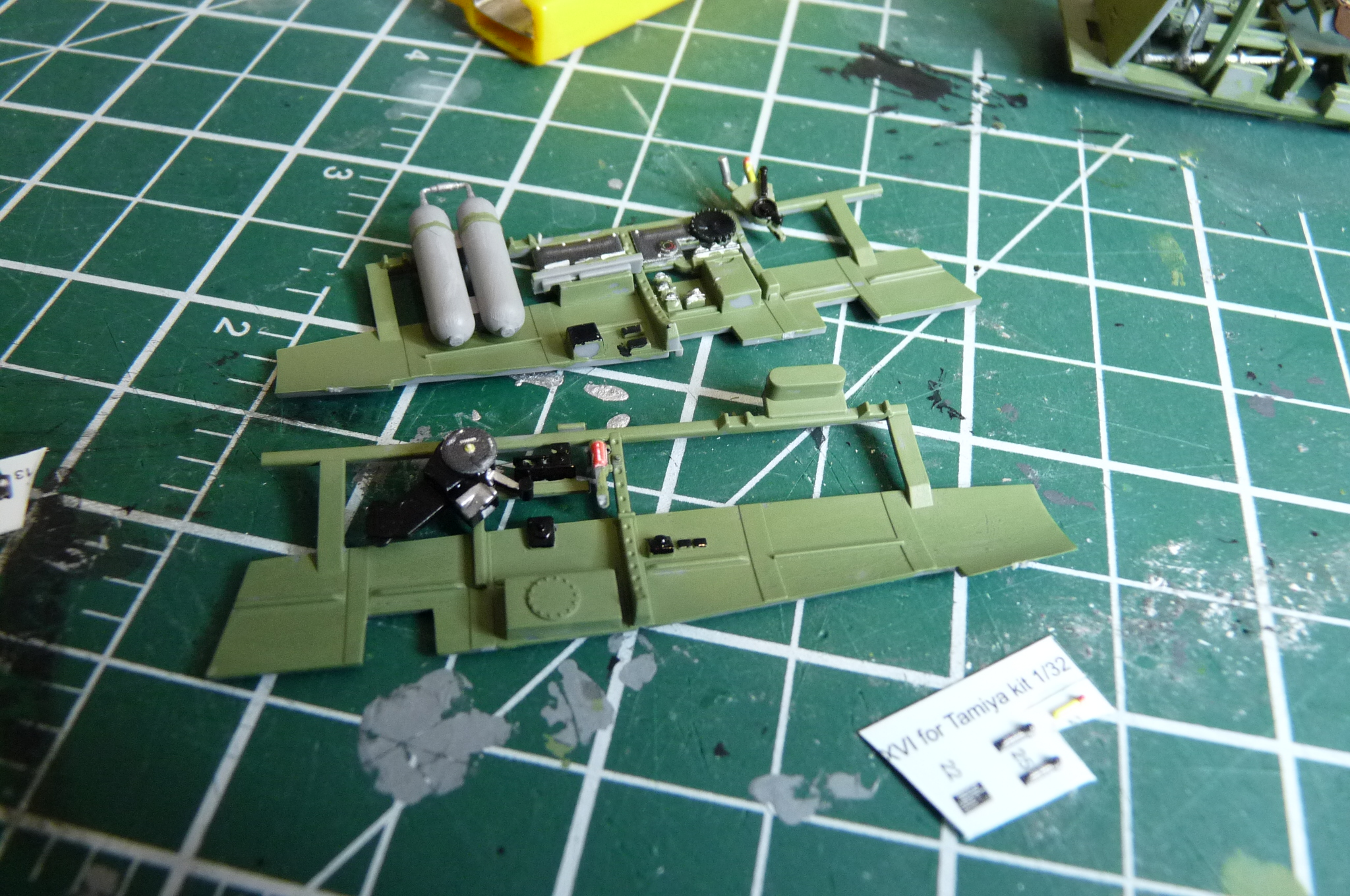
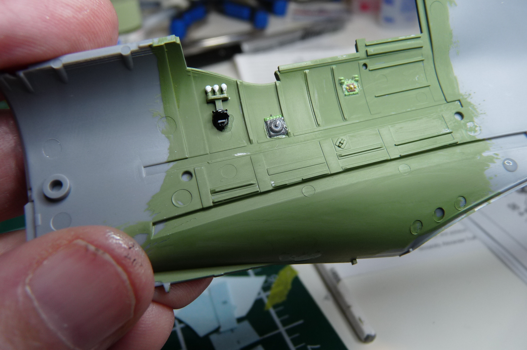
The right cockpit sidewall, in progress. Two Quinta decals middle and rear, and a kit part I painted at front (left side in photo). That part, with the three white knobs, is an example of a difference between the A, B, and C variations in thi
 s kit.
-
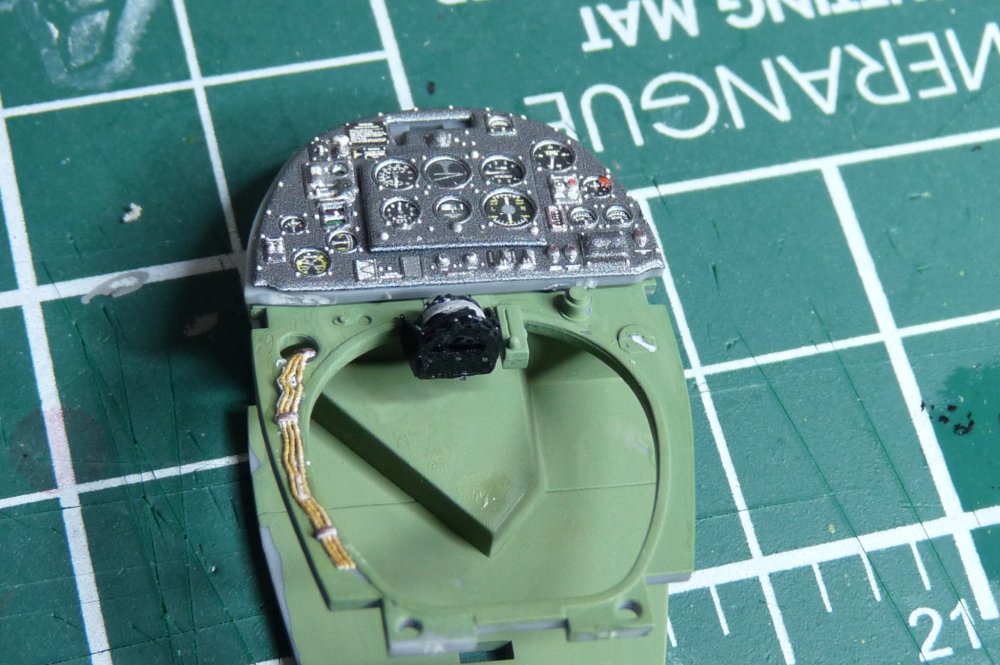
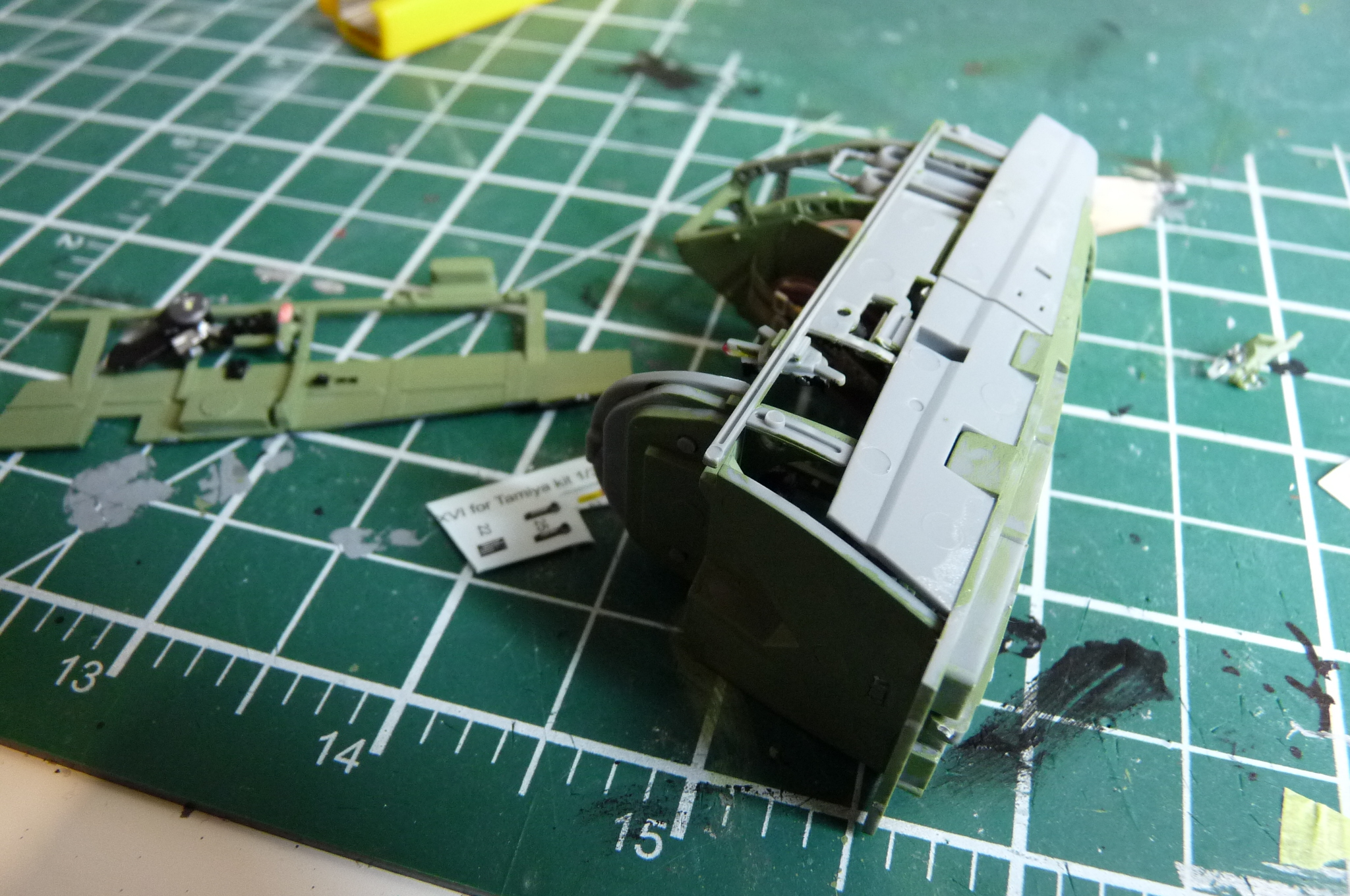
Here you can see I've scraped off the raised detail below the MIP, so I can put on the Quinta decal that represents it way better than the kit could. I also love the wire bundle poking out of the green part below the MIP. Another Quinta decal. I've never been able to do a Spitfire so well, and so easily. Quinta is well worth the investment.
Sorry for the fuzziness of the rudder pedal pic. In a way it illustrates just how small some of the detail is. Quinta provides some green corrugated pedal covers, adding additional realism. In this photo, you can see 3 of 4 installed, with CA glue on the top right ready for the last one.


.jpg.1d5a78193834023378ea4fadf92b948f.jpg)
.jpg.672c732ee3bde1dc6b6e887b55c5c340.jpg)


1/32 Inspirations …..
in In-Progress Pics
Posted
Very nice. Have you thought of doing the F-5A? Tan Model seems to have given up on that project. How much are you charging for such 3D prints?
ALF