


Raptor71
-
Content Count
112 -
Joined
-
Last visited
Content Type
Profiles
Forums
Calendar
Posts posted by Raptor71
-
-
6 hours ago, habu2 said:
That bottom photo must be from one of the early static mockups that LM toured around. The gear hinges etc look nothing like the production jet.
Edit: that would also explain all the zap stickers...
.
Yes, but I entered the photo to show the area with two different heights. The fact that it is a static model is not relevant as that part corresponds to series specimens. If the front wasn't deeper, the trolley wheel couldn't stand on it.

-
17 ore fa, MikeDadofFour ha detto:
Il mio commento si applicava a qualsiasi produttore. Forse le connessioni elettriche e fluide non possono essere facilmente determinate, ma la forma generale che probabilmente si svolge su tutti e tre i modelli di F-35 avrebbe potuto essere rappresentata più fedelmente. Ecco un'immagine che ho trovato.
È un'opportunità di miglioramento da parte dei guru della resina e della stampa 3D là fuori.
Se l'Italeri F-35B si adatta così bene, forse ci provarò dopo aver finito il kit KH.
Grazie per la recensione Dave!
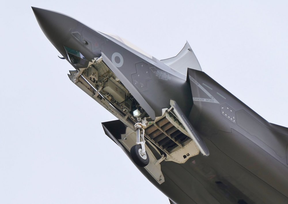
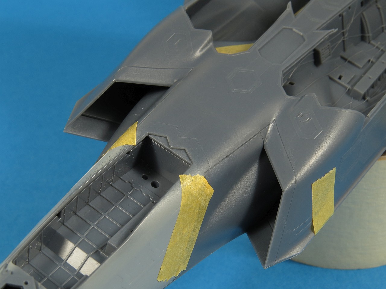
The front carriage compartment of the F-35A/B has greater depth in the front. There is an inclined plane that connects the front with the back. The Italeri Kit does not have this feature, the Meng kit yes.

-
On 8/26/2022 at 11:04 PM, YKM said:
What I would like to see someone work on...
765022de9387d73f143a3813f3da43aa (1284×1169) (spot.im)
Whatever it is, it's becoming common enough to believe that it may be standardized as part of the F-35 Blk.4 and the F-22 MLU. The checkerboard pattern is too small and varied in its tesselation patterns to be accomplished by hand masking or even templates alone. It's going to have to be printed. And it's going to be expensive when it is, especially at 1/48th and above.
As you can see, it makes the entire airframe look, not metallic but translucent blue or purple.
It's hard to imagine doing an entire airframe in decal, especially one compromised by so much raised RAM paneling. Rather like the 'Hentai' kits from Hasegawa a few years back. But, increasingly, that's what it's looking like it's going to have to be.
Thoughts?
First of all it is an F-35C. I consider (owning it) the F-35C Kitty Hawk in 1/48 scale "insufficient" and I will wait for new kits. second thing it is a unique specimen of the experimental VX-9 squadron. Third, that coating has no thickness on a 1/48 scale model, so it can only be reproduced with a decal or masking. If I had to make it (I really like it) I would do a 3d scan of the kit and then I would design the shapes to be used as templates for masking at CAD. It’s not something I’ll consider before I see a new F-35C kit. My hope is that Meng will do it whose F-35A is really very accurate and with few mistakes.
-
4 minutes ago, Bsin said:
Will you make these parts Is commercially available?
Once realized, if someone wants information they can contact me in private.
-
17 minutes ago, Janissary said:
Thanks for these details. They are enjoyable to review. One slightly off-topic question for everyone in the knowing:
This is about Meng F-35A. When I joined the upper wing halves to the upper fuselage, I got a noticeable dihedral:
Granted, I did not glue the upper to the lower halves yet, so that may bring the wings down a bit, but I was surprised and started to question my assembly.
So the question: In the real thing, are the wings simply parallel to the ground all the way from the wing root to the wing tips, or do they bend up a little at the wing roots to create a slight positive dihedral?
thanks.
I recommend gluing the two upper parts of the wings and fuselage. The wing dihedral will be 0. Then the lower part of the fuselage will beglued and only at the end the lower part of the wings. For any model that has this piece breakdown I use this method. It will be necessary to intervene with file or other roughing tools to force the wings into the right position.
-
21 minutes ago, TheGloriousTachikoma said:
Despite my winging I had put this kit on my list because it's a cool kit...this strikes it back off hard.
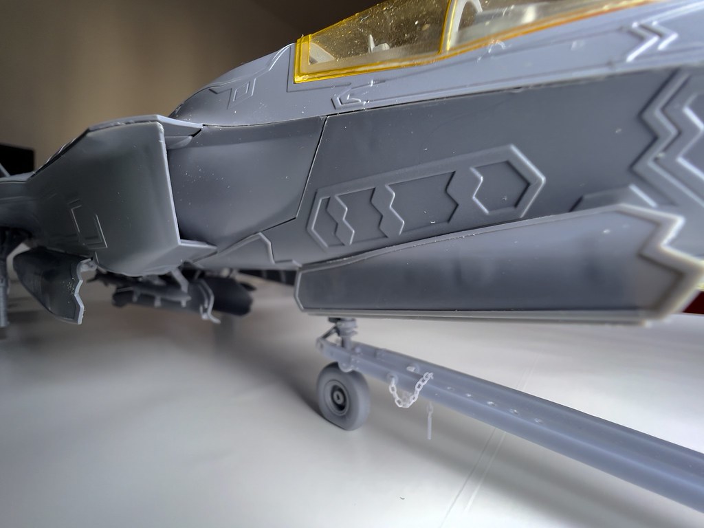
I find it a decent kit, much better than the Kitty Hawk, both in general appearance and details. It also has a good breakdown. RAM coating in my opinion is not a big deal. You will notice much less in a painted model, keep in mind that the photo is taken wide angle so the defects are accentuated. It's a kit I would recommend if you want an F-35B. I expect a big improvement in appearance with the 3D parts I will design.
-
Yes... RAM coating is too thick. Keep in mind that I assembled the model with vinyl glue so that I can check the parts and be able to "disassemble" it when I proceed with the construction.
-
-
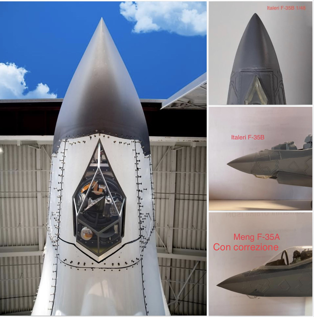
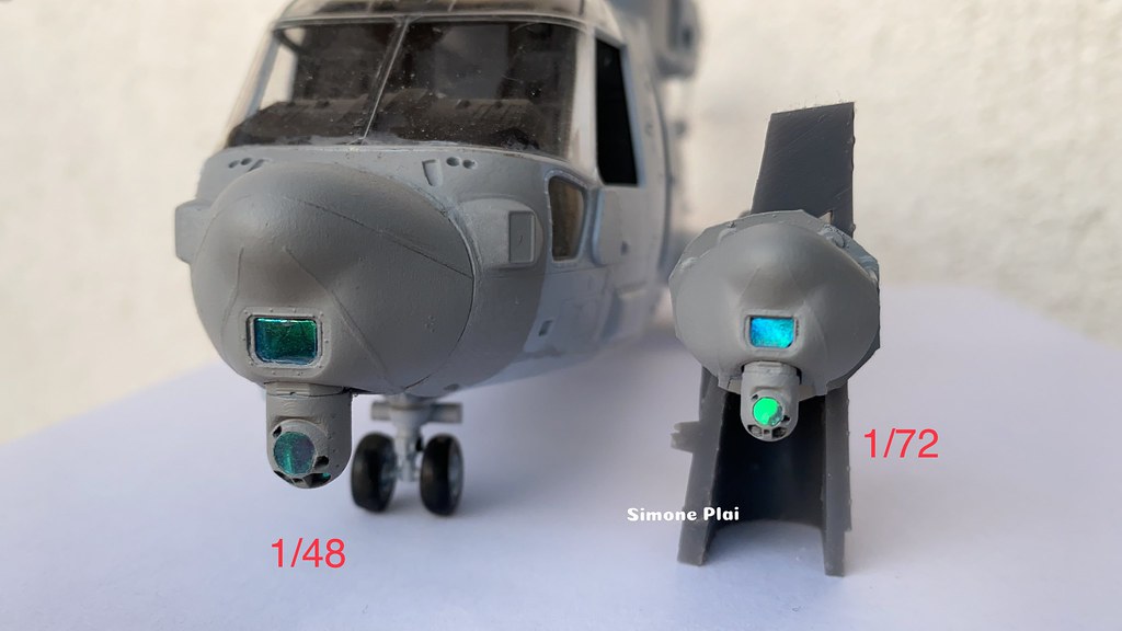
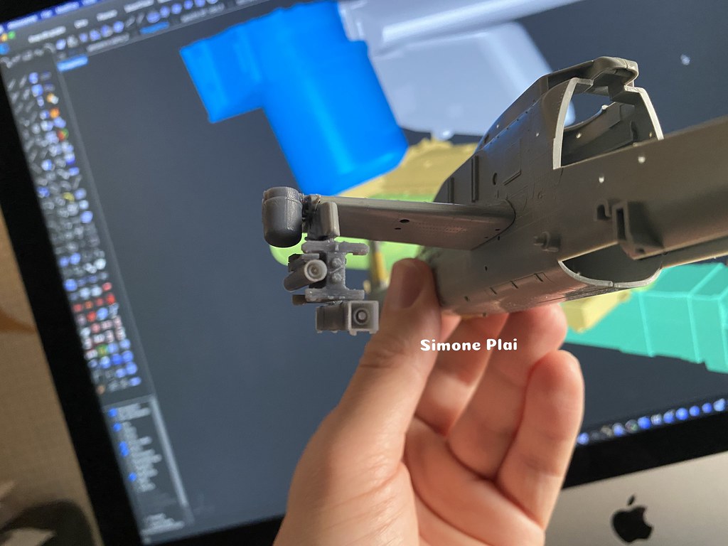
Radome…
-
Front

-
Test with STT
-
I received my F-35B and analyzed it with the photogrammetry and other instruments I have. I will also need to intervene on horizontal stabilizers. Their correct inclination is about 5°, while on the Italeri model it is 8°. You can "force" the inclination and glue them in the right inclination, but then they don't connect well with the fuselage and I don't like the result. The Kitty Hawk kit also had this problem. My solution will be the 3D design of new horizontal stabilizers, where it will also be possible to adopt the "lowered" position they assume in vertical landing and takeoff. The video highlights a further reason for me to also make the vertical rudders, on the Italeri kit in addition to the dimensional problems already reported, they have a wrong inclination of 26 °, while the correct one is about 21 °. The profile in the view from behind also highlights a wrong shape. Note that on the Meng F-35A model (I remember that horizontal stabilizers and vertical drifts are "equal" on the F-35A and B these parts do not have significant differences and are substantially correct.
-
On 5/5/2022 at 9:10 PM, Helmsman said:
Arrived. Looks great.


Metal pitot tube is not included right?
-
-
On 10/1/2021 at 5:40 PM, eflight said:
Great CAD and print work
Would love to make a larger version to go with RC planes
Do you have a good source for 3 view drawings of the STT that you can share?
TIA
I'm sorry but I didn't use drawings to make it . Photos and photogrammetry.
Simon.
-
1 hour ago, JeffreyK said:
They look excellent! Are these showing 1:35 or 1:48? I saw your post on Facebook on the 1:35 version. Personally, I'd only be interested in 1:48...are you making any available for purchase or only your own personal use?
Cheers,
J
The model of these photos is in scale 1/48 ( that I will probably use with the F-35B Italeri as soon as it comes out). I’ve already printed the 1/35 version and I’m assembling it and I’d like to use it with KH’s AH-1Z Academy and Seahawk. For other information you can contact me in private.
-
19 hours ago, Paul Boyer said:
3D printed I presume?
yes
-
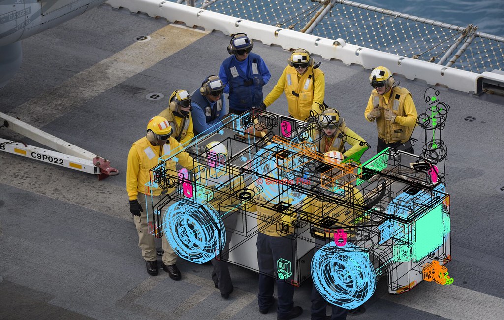
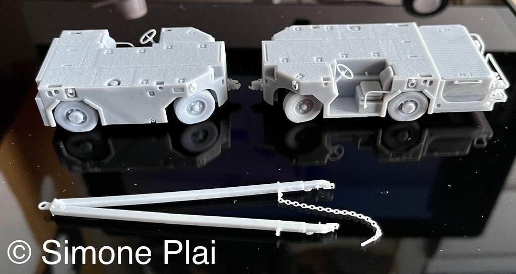
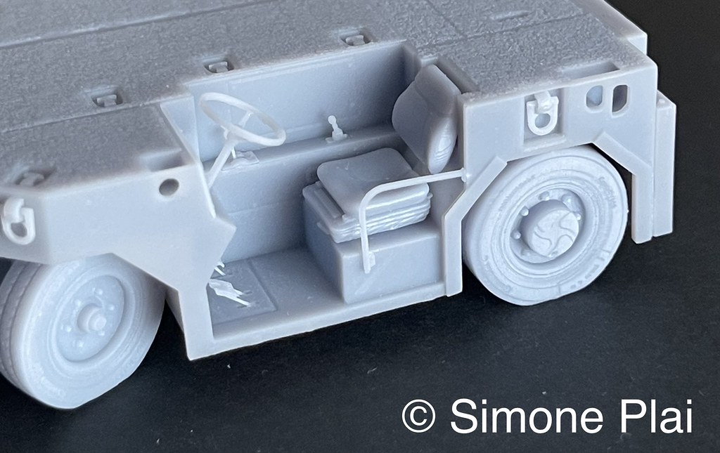
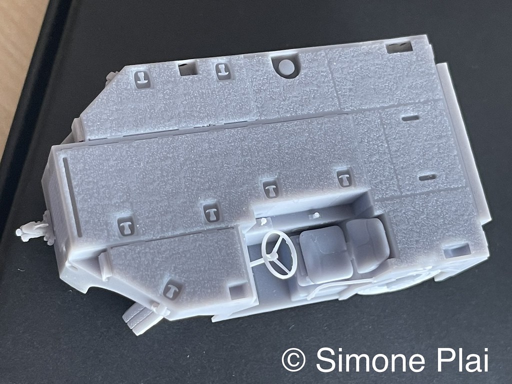
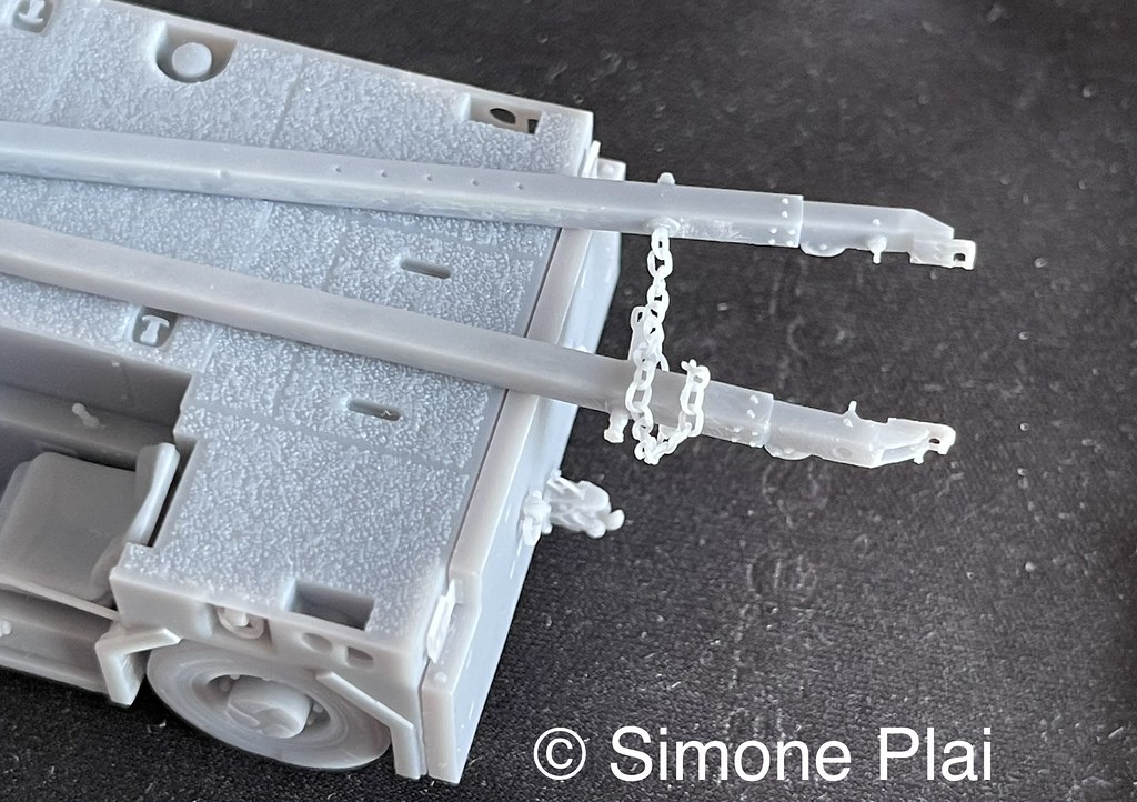
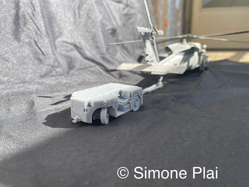
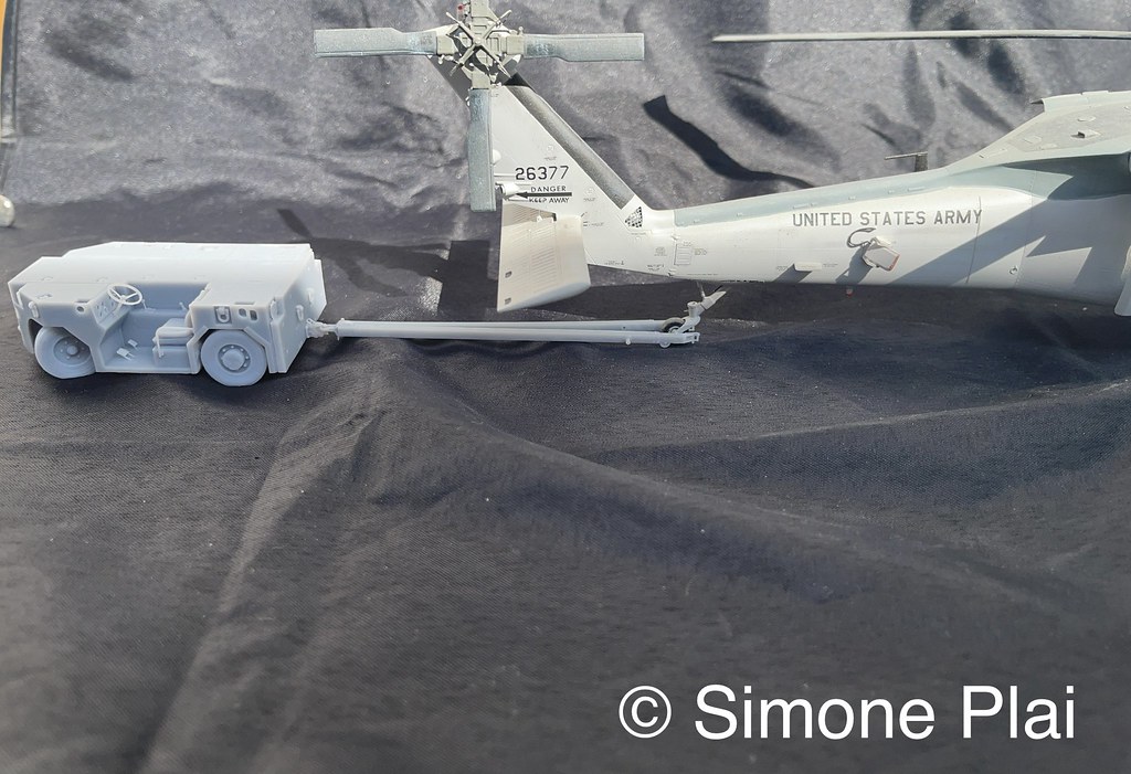
Hello to you all. My latest project, aircraft towing tractor and helicopters SST A/S32A-49 with MSU ( aircraft universal starting unit) and ALBAR trailer in scale 1/ 48. I can use it for US NAVY and MARINES aircraft such as F/A-18 Super Hornet, E-2 Hawkeye, all S-70 Hawk models on board, the recent MV-22 Osprey HB, AH-1Z Zulu Cobra, UH-1Y Venom etc. I will also make it on a 1/35 scale for my recent AH-1Z Academy and future S-70 Hawk purchases.


-
On 6/19/2020 at 8:17 PM, Solo said:
Ok, but my question was not why they don't make such subtle lines at all, because they can make them at all.
I am curious why they don't make them on whole kit.
Please check out this part of nacelle of Su-35.One line is fine and subtle, second one, next to it - is not.
The same I can say about panels.
The different thickness of the rivets depends on the use of cnc machines with 3 axes (rivets with different thicknesses as the engraver can be tilted) or 4-5 axes (rivets with the same thickness as the engraver can be tilted and remain parallel to the surface to be engraved)).
-
-
I am making several parts for my Merlin Airfix.


-
18 hours ago, Whiskey said:
How's the Spike's coming along?
Something that I caught while doing some research earlier is that the Army has stopped everything regarding the APKWS. Probably makes sense of why they are pursuing the Spike now.
https://breakingdefense.com/2020/02/army-kills-apkws-rockets-mystery-missile-mirm/
I have already printed the system in 1/48 and 1/72 scale for the Apache. Then I will also do it for the Venezuelan Black Hawks Arpia 4 (which have the data link antenna on the left pylon with a specific adapter). The APKWS system is simply a laser kit which is applied on 2.75 "rockets, costs approximately $ 22,000 and has a range of approximately 8000m. The Spike system that is being tested on the US Apache is in the long range NLOS version. It has a port of approximately 25 km and costs over $ 300,000. This missile is used in a very specific way. It is generally launched from behind a hill or mountain, in order to make itself "invisible". the missile has a fiber optic cable which in this case only serves for the first few kilometers. Then the cable is cut and the missile is guided by the operator thanks to all the links to the antenna data installed on the right wing of the Apache. I am attaching a video that I find interesting. https://www.youtube.com/watch?v=QPK4dPX4lsQ&t=434s
-
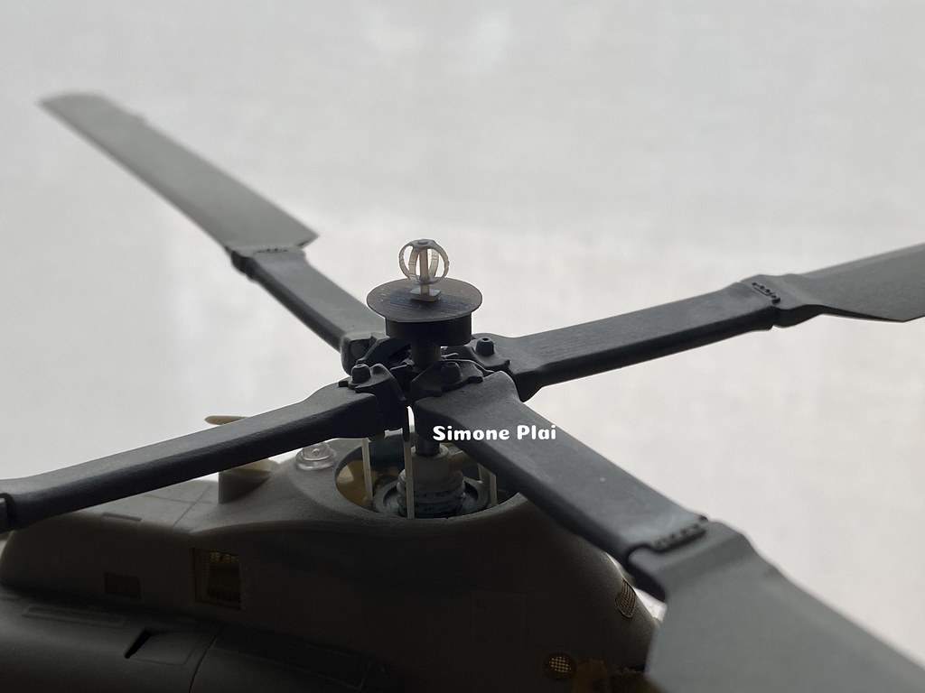
I designed this in 3D and I printed my UH-1Y and AH-1Z. Hope you like it.
The antenna on the right in the 3d image is for Apache, Black Hawk etc. The one for UH-1Y and AH-1Z is shorter, as well as having support for the rotor hub.


-
I installed the Spike system on the wing of the Apache HAS in 1/48. How do you like it?


Danish merlin question.
in Helicopter Modeling
Posted
For my models, I also made the Norwegian AW101 SAR version in 1/72 scale. The video is 2 years old and some parts I added are missing, which would be the secondary winch and the tail sensor. You can see them in the video of the 1/48 scale version.