

spaceman
-
Content Count
2,877 -
Joined
-
Last visited
Content Type
Profiles
Forums
Calendar
Everything posted by spaceman
-

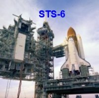
Space Shuttle Launch Pad 39A with Challenger STS-6 (1:144)
spaceman replied to spaceman's topic in Real Space Modeling
Hi together, so, let's go to at last thicker SSWS pipes and the associated supports. For this I can initially resort to my erstwhile pull-ups before the conversion of the SRB holes when I had started already with the SSWS. Who wants to track once more precisely, can please scroll back to pp. 25 (#493). Unfortunately, I can forget my former pipes (1:160) as they are a little too narrow and too short for the 1:144 holes. In the following general layout drawing the position of the pipe supports of the 24'' line (Ø 4,0 mm) is marked, and there are respectively 18 supports around each SRB -
Caution, by using this thin Styrene you must however be careful and heat gently and evenly all around. It is important that the heated Styrene must cool in the desired shape in order to retain this shape. Or you can dive the cone in a hot water bath, press down carefully, and then pour the water but still pressing down the cone until cooling.
-
Hi Mike, yep, then have good luck, you would certainly have a lot of fun.
-
Space Shuttle Launch Pad 39A with Challenger STS-6 (1:144)
spaceman replied to spaceman's topic in Real Space Modeling
Thanks Mike for your great compliment, but my home is my museum, since NASA has no chance. -
Space Shuttle Launch Pad 39A with Challenger STS-6 (1:144)
spaceman replied to spaceman's topic in Real Space Modeling
Thanks Pete. Hi there, the question of the space for the SSWS line above the angled nozzles but has left me no rest, so I had to check out right now of its dimensions. Here you can see this place. For the thick ring line (24''), coming from the left, I will use a rod with Ø 4,0 mm. The tubular transition then has Ø 2,5 mm and tapers in front of the TSM to Ø 1,8 mm, where are sitting further eight nozzles. Source: NASA And here I have tried with such a profile Ø 1,8 mm if that still will fit through the gap under the ladder and behind the angled nozzle, and it fits actually what no -
Space Shuttle Launch Pad 39A with Challenger STS-6 (1:144)
spaceman replied to spaceman's topic in Real Space Modeling
Thanks Mike for your nice words. I am glad that you like my work and you still stay tuned. But you are also a friend of tiny details and know as well how much patience for such crazy things is necessary, when I think of your incredible job with the thousands of tiles and blankets. No pain no gain! -
Space Shuttle Launch Pad 39A with Challenger STS-6 (1:144)
spaceman replied to spaceman's topic in Real Space Modeling
Thanks bubble for your nice compliment, this Firex line with its tiny supports and nozzles was a crazy stuff, but the effort was worth it and I'm very happy with the result so far. -
Space Shuttle Launch Pad 39A with Challenger STS-6 (1:144)
spaceman replied to spaceman's topic in Real Space Modeling
And after that I tried on this angled nozzles, and glued together with the three nozzle pipes with MEK. And now to the nozzle stubs, whereby the insertion of these tiny parts with the tweezers into the holes was extremely stressful, which has not always worked right away. But finally all 25 nozzles were then installed, and the sight of this bizarre structure will be quite impressive, I think. And for today as a crowning finale the picture with two TSMs which compensates for all effort. That's it for today. -
Space Shuttle Launch Pad 39A with Challenger STS-6 (1:144)
spaceman replied to spaceman's topic in Real Space Modeling
Hi there, first I have to add the nozzles on the branch line in front of the LOX TSM, with which the two branch lines are now complete. Then, as already announced, now to the clamping rings I've bent of 0.3 mm lead wire. On the back of the Firex main line there are six of them, two of them sit in the middle, next to the two single supports, and the other four between the support pairs. Then I pre-drilled the holes for the nozzles (Ø 0,5 mm). Since one can easily slip during drilling on the thin line (1.2 mm diameter) but that line was fixed again in a proven manner. And then I s -
Since one can only marvel at how you do that, very impressive.
-
Space Shuttle Launch Pad 39A with Challenger STS-6 (1:144)
spaceman replied to spaceman's topic in Real Space Modeling
And now also the supernatants can be tapped off, first the parts in front of the line, and then behind them. And so have already done the ten supports. And as you can see, it all fits together well and still does not look bad. And tomorrow it will become funny, then the tension rings and the remaining nozzles are waiting for me. -
Space Shuttle Launch Pad 39A with Challenger STS-6 (1:144)
spaceman replied to spaceman's topic in Real Space Modeling
Hello guys, and thus continue on the back of the Firex main pipe where there are similarly structured supports and a lot of nozzles. The difference can be seen well on the next two panorama pictures, although you have to look closely. Source: NASA The base plate is screwed just at the end on the Blast Shield, the front is significantly narrower and the rear supernatant is minimal. Source: NASA Consequently, my supports look somewhat different from the front and consist of three parts. For the substructure I've composed a Styrene Strip 0,25x1,0 mm (length) and a strip 0,25x0,75 mm (s -
Space Shuttle Launch Pad 39A with Challenger STS-6 (1:144)
spaceman replied to spaceman's topic in Real Space Modeling
Hi there, today I will continue. At the branch line in front of the LH2 TSM still missing the spray nozzles. For that I have used the thinnest Evergreen rods Ø 0.5 mm and sharpened the front slightly. And on this occasion I have mounted the clamping ring of 0.4 mm lead wire at the end. Then I carefully pre-drilled the holes, then plugged in the nozzle stubs and glued with MEK. And so does the environment around the SSME shaft around slowly take form. So far so good, and so as not to come only out of practice, I have done the supports of the other branch pipe in front of the LO -
Space Shuttle Launch Pad 39A with Challenger STS-6 (1:144)
spaceman replied to spaceman's topic in Real Space Modeling
Hey Guys, and because I love this tricky details so, I have dared and decided for this T-shaped pipe supports on the Firex-line Source: NASA and therefore measured the geometry on the basis of the close-up image again in more detail. Source: NASA Then I've made a new T-beam by gluing an Evergreen Strip 0,5x0,5 mm on a handcarved Styrene Strip 0,2x0,7 mm, from which I carefully have tapped off 1 mm "long" stubs. That worked still relatively good, but the gluing of these midgets was then nothing for the faint hearted and succeded only with bated breath between two heartbeats. Aft -
Space Shuttle Launch Pad 39A with Challenger STS-6 (1:144)
spaceman replied to spaceman's topic in Real Space Modeling
Hi there, so, today I will continue with the front two branch lines, the assembly process I have specified once more. Now I want to build the branch lines with the supports and nozzles separately and then mount on the main line, and finally all should be painted together. In addition I have been a little bit experimenting with the structure of the supports. The supports are sitting on a base plate that is bolted to the Blast Shield, and support the tube only on the outside, as you can see in this picture. Source: NASA And this structure, I have tried to replicate in different version -
Space Shuttle Launch Pad 39A with Challenger STS-6 (1:144)
spaceman replied to spaceman's topic in Real Space Modeling
Thanks Mike for your compliments, yep, that's really a tricky matter. -
Just awesome, very impressive way! Keep up your cool work, I'll stay tuned!
-
Hello LUT friends here is the new update of LVM Studios of the production of the first prototypes for the Mobile Launcher. First prototype parts For cost reasons, the substructure is now not made of Styrene but from MDF, which is a medium-density fibreboard, but which ensures sufficient stability. The outer cladding consists however of Styrene. The side walls have channels to which Evergreen profiles can be glued. In addition, color tests were carried out, at which I suppose but strongly that the parts are supplied unpainted.
-
Space Shuttle Launch Pad 39A with Challenger STS-6 (1:144)
spaceman replied to spaceman's topic in Real Space Modeling
Hi there, but before I start tinkering these details to my so laboriously bent Firex-line, I tried different things in advance as a precaution, so there are no nasty surprises. This concerned initially once the pre-drilling of the pipe and glue the spray nozzles. And when handling this specimen it actually came to feared kinking at one point that was drilled through. That is why I again drilled in the next experiments only with a few turns and this time tried yet to prick up the nozzle ends after gluing slightly. This is a bit tricky because of the danger of breakage and also risky, b -
One more time to your experience with XTC-3D, I had asked you three weeks ago in an other thread (Shapeways best resolution?): What do you think about, that the coated surface would still require a final finishing by sanding?
-
Yep, click on the photo above, it's WSF.
-
Hi Mick, this is an awesome scale, incredible. It is the Design by Max Grueter, right? Can't wait to see the painted guys on the entire Diorana. This becomes another tidbit, I'm sure.
-
Space Shuttle Launch Pad 39A with Challenger STS-6 (1:144)
spaceman replied to spaceman's topic in Real Space Modeling
Hi all together, but nevertheless I think it should be feasible, although it already is in the area of very small dimensions, what concerns the Water Nozzles. They are 0.5 mm in diameter, i.e. I also have to pre-drill the thin pipe (Ø 1,2 mm) with about this diameter in order to put the nozzles. And because thereby the cross section is fairly weakened, the line could already become quite unstable. That's why I tried this on a sample piece. And as you can see, the test was successful, one just has to be careful not to pierce the line. So please press again thumb and stay tuned! -
Space Shuttle Launch Pad 39A with Challenger STS-6 (1:144)
spaceman replied to spaceman's topic in Real Space Modeling
Hello Guys on Sunday, and thus back to the tricky narrow and short bends above the Blast Shield, only this time on the other side, so everything is reversed. And so the secure clamping of the line between the balsa boards slowly becomes already a delicate matter, because the need to sit tight as possible and must not move when bending under the hot-air shower. In addition, you must now somehow protect the neighboring areas of the line too, because otherwise the rest could be deformed when it gets too hot in the vicinity, and then all the effort would have been for nothing. But that's -
Thanx Pete for all your kind and encouraging compliments. The work and skill you and the other guys have demonstrated on your builds have been giving new inspiration to me always again.