

spaceman
-
Content Count
2,877 -
Joined
-
Last visited
Content Type
Profiles
Forums
Calendar
Everything posted by spaceman
-

Space Shuttle Launch Pad 39A with Challenger STS-6 (1:144)
spaceman replied to spaceman's topic in Real Space Modeling
No understatement needed, Kirk. PM me a link for having a look at it. -
Space Shuttle Launch Pad 39A with Challenger STS-6 (1:144)
spaceman replied to spaceman's topic in Real Space Modeling
Better you have than would have. -
Space Shuttle Launch Pad 39A with Challenger STS-6 (1:144)
spaceman replied to spaceman's topic in Real Space Modeling
Thanks Mike, yep, I have posted about those ladders February 16, which are offered by ABER (1:200-05) as Ships Ladders (wide) in three different widths, of which the middle width (3,5 mm) is well suited for my Payload Canister (1:160). There one can also find other great PE sets as Stairs, Railings, etc. Have a look at their website: https://abermodels.com/ -
Space Shuttle Launch Pad 39A with Challenger STS-6 (1:144)
spaceman replied to spaceman's topic in Real Space Modeling
Hello everybody, initially I've cut the remaining three ladders to the length (14,5 mm) with a side cutter. And therewith without many words to the next ladder, which truly went a little easier because I knew what I had to pay particular attention to. Nevertheless, two feet didn't want to glue at the ladder stringer straight away, which is why I first had to carefully remove the old CA from the foot before the second gluing could take place, which then worked well. But one shouldn't let that impress you, otherwise t -
Space Shuttle Launch Pad 39A with Challenger STS-6 (1:144)
spaceman replied to spaceman's topic in Real Space Modeling
Thanks Kirk, what kind of 1:24 diorama you are working on? -
Space Shuttle Launch Pad 39A with Challenger STS-6 (1:144)
spaceman replied to spaceman's topic in Real Space Modeling
Hello everybody, after trying hard but ultimately unsuccessfully to cut feet of the same length out of the brass strip (0,2 mm x 1 mm), I changed my mind and cut out a Styrene strip (0,15 mm x 1 mm) instead, from which I then cut the 1,5 mm long feet with the Chisel cutter at the Ruler angle stop. The feet were glued to the ladder rails according to my tested fixation between several rulers, whereby the underside of the ladder with the rungs must point upwards so that the feet are flush with the top edge of the rails. Great care -
Space Shuttle Launch Pad 39A with Challenger STS-6 (1:144)
spaceman replied to spaceman's topic in Real Space Modeling
Hello everybody, and thus a look at the next details, which are first the two white Pipes of the Output shafts on both sides of the Bevel Gearbox, as well as the two Pneumatic lines, whose dimensions I have determined in this image. Source: NASA (STS-135) After that, the pipes have a diameter of Ø 0,3 mm, and the pneumatic lines are still a little thinner with Ø 0,2 mm. For this I will use the thinnest available Styrene rods (Ø 0,3 mm) and Nickel Silver rods (Ø 0,2 mm). But before I lay those pipes and lines, I'll f -
Space Shuttle Launch Pad 39A with Challenger STS-6 (1:144)
spaceman replied to spaceman's topic in Real Space Modeling
Thanks Mike for your nice compliment. Patience is one thing, the iron will to succeed is another. And then I always say to myself, never give up and ever keep fiddling about a feasible solution! -
Space Shuttle Launch Pad 39A with Challenger STS-6 (1:144)
spaceman replied to spaceman's topic in Real Space Modeling
Hello everybody, and finally to the remaining three hold-downs, which I've put off for as long as possible because of the stressful fiddling. First I've bent all Rungs (Ø 0,2 mm) and didn't even notice that I already had one too many, but better than one too few. After the lateral discs were glued and drilled out, the marking of the midpoints for the rung drilling followed, for which I used a pin. But even this simple matter is not trivial and didn't want to work right away, because it's about tenths of a millimeter and one needs a steady hand -
1/32 Command and Service Module (CSM)
spaceman replied to crackerjazz's topic in Real Space Modeling
Hey Joe, congrats for your fantastic job, together with your cool 3D printer! Great progress, meanwhile you both seem to be a perfect team! -
Space Shuttle Launch Pad 39A with Challenger STS-6 (1:144)
spaceman replied to spaceman's topic in Real Space Modeling
Hello everybody, here is still a small addendum to a detail on the Port Side, where below the Personnel Door is still located this Access Platform Mounting Bracket, which I have added. Source: NASA (STS-125) The Bracket (0,13 mm x 7 mm) stands on tiny Base plates (0,13 mm x 0,5 mm x 1,5 mm), whose gluing together was quite tricky. Here is the test fitting on the canister together with the two ECS Ducts. And then there are still these Horizontal Transportation Tie-down Lug Plates -
Space Shuttle Launch Pad 39A with Challenger STS-6 (1:144)
spaceman replied to spaceman's topic in Real Space Modeling
Hello everybody, and after the same knitting pattern briefly to the announced ECS Supply Duct, for which the Pipe bend on the Connection nozzle has to be glued rotated by 90°, wherefore the parts on the right are already prepared. To the left is the finished ECS Return Duct. After the Connection nozzle was glued onto the Ring plate, came the decisive step, in which this time the pipe bend had to be glued lengthwise with the foot of the connection nozzle onto the ring plate, which was then glued lengthwise onto the bas -
Educraft Diversions Apollo Era Crawler Transporter - 1/144 Scale
spaceman replied to Logan 5's topic in Real Space Modeling
Hi Al, here you can seen the real walkway mesh and determine the mesh size of a better suitable grid. Source: nasatech.net Maybe such a 40 Mesh stainless steel grid. Source: mallametalica.es -
Space Shuttle Launch Pad 39A with Challenger STS-6 (1:144)
spaceman replied to spaceman's topic in Real Space Modeling
Hello everybody, and thus to the shortening of the Tube turns for the two ECS Ducts, whose dimensions are summarized here again. Source: NASA (STS-104) In view of the small dimensions of the arches, it quickly becomes clear that after cutting the bent round rods (Ø 2,5 mm) to the different lengths, not much of them will remain, what becomes clear after the cutting marks been attached. A firm fixation is required for cutting through the rod, which is why I clamped it in the Mini vise (Proxxon). Then the marking was carefully scor -
Space Shuttle Launch Pad 39A with Challenger STS-6 (1:144)
spaceman replied to spaceman's topic in Real Space Modeling
Hello everybody, and thus to the ECS Supply and ECS Return Ducts of the canister, which are connected via the red hoses to the Environmental Control System (ECS Module) of the transporter. It's starting with the two white Connecting nozzles firmly connected to the canister with the Tube bows welded from five segments, whose dimensions I've determined from this photo. Source: NASA (STS-130) There one can see that the connecting nozzles sit on thin Base plates (0,13 mm) and that the tube bows are attached to nozzles with Clamping rings, which -
Space Shuttle Launch Pad 39A with Challenger STS-6 (1:144)
spaceman replied to spaceman's topic in Real Space Modeling
Thanks Mike for your nice words, well, Real Space Modeling is my great passion and works like a drug, from which I just can't get away, especially since I keep discovering new and interesting details of this ingenious technique. But don't worry, a possible infection with this virus is completely harmless. -
Space Shuttle Launch Pad 39A with Challenger STS-6 (1:144)
spaceman replied to spaceman's topic in Real Space Modeling
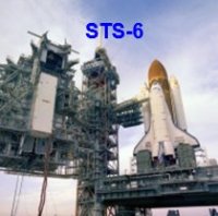
Hello everybody to early hour, today is a memorable day in the history of manned US Spaceflight, because on April 4th, 1983 Space shuttle Challenger took off with its crew on its maiden flight STS-6, Source: retrospaceimages.com (STS-6) L-R: Donald Peterson †, Paul Weitz †, Story Musgrave, Karol Bobko Source: wikipedia.org to which I have dedicated my long-term project, with which I'm going already into the 12th year. Source: nasa.org And as luck will it, on the day of the 40th Anniversary, in the 50th year -
Space Shuttle Launch Pad 39A with Challenger STS-6 (1:144)
spaceman replied to spaceman's topic in Real Space Modeling
Hello everybody, now that the Handrails are safely stowed away until they are glued, I once again looked at the various doors, hatches and instrumentation panels on the canister. Although these are only small optical details, they give the canister its own face and should not be missing. From these details I then printed out true-to-scale copies from original photos and glued them on. First, there's this Personnel Door on the Forward Bulkhead of the canister, Source: forum.nasaspaceflight.com (STS-9, Ares67) which has to be tight and therefo -
Space Shuttle Launch Pad 39A with Challenger STS-6 (1:144)
spaceman replied to spaceman's topic in Real Space Modeling
Hello everybody, and these Mounts were glued today. At it the most difficult step was pushing the Handrail feet into the tiny mounts, which is why I "sharpened" them slightly. Then the gluing followed with MEK by carefully wetting the mounts with the finest red sable brush (10/0). This also finished the third Handrail pair, and could be placed on the template for fitting. It was finally the turn of the last couple, whereby the whole set is f -
Space Shuttle Launch Pad 39A with Challenger STS-6 (1:144)
spaceman replied to spaceman's topic in Real Space Modeling
Hello everybody, today the Mounts were glued to the other three-legged handrail, wherewith the row at the bottom of the canister is complete. Then it was the turn of the two vertically arranged handrails above it, which have two mounts and were done more quickly. And so the image slowly completes, whereby I also still hinted the Personnel door through which one can arrive the Canister Payload Bay. Now only the mounts on the four upper railings are missin -
Space Shuttle Launch Pad 39A with Challenger STS-6 (1:144)
spaceman replied to spaceman's topic in Real Space Modeling
Hello everybody, and with it to the Final Cutdown. This was the chosen arrangement for the second half of the brackets for cutting off the U-profiles (1 mm) that I had previously scratched and marked with a pencil, here after careful cutting with a razor blade under sharp eagle eyes. And that's my valuable yield of 20 mounts (2 reserve) with approximately the same size. I had imagined the gluing of the mounts onto the handrails to be a little easier, but firstly it turns out differently, and -
Educraft Diversions Apollo Era Crawler Transporter - 1/144 Scale
spaceman replied to Logan 5's topic in Real Space Modeling
I've been saving started posts (text & jpgs) in MS Word for a long time, better you have, than you would have. -
Space Shuttle Launch Pad 39A with Challenger STS-6 (1:144)
spaceman replied to spaceman's topic in Real Space Modeling
Hello everybody, let's go on with the production of the tiny Handrail brackets, which are held up the progress quite a bit, since you always have to let the glue dry before you can handle them any further. In the meantime I have arranged the steel block the other way around when cutting off the end strip, as this way I can better control the cut with the razor blade. The tricky separation of the U-profile can also be done in different ways, which is why I tried out a few things and switched to a larger sheet of steel as a base, whi -
Educraft Diversions Apollo Era Crawler Transporter - 1/144 Scale
spaceman replied to Logan 5's topic in Real Space Modeling
Hi Al, that looks good already, keep it up and don't give up, even if it gets tricky anytime. -
Space Shuttle Launch Pad 39A with Challenger STS-6 (1:144)
spaceman replied to spaceman's topic in Real Space Modeling
Hi Mike, you are one of my most loyal companions all time and I know you've been in there from the start, which is why I looked back. That was 11 years before almost to the day (03/15/2012), what a long and memorable time to look back on fondly. And you were the second interested modeler after Bill (niart17) to reply that time. You also recognized early on the difficulties of the scale dilemma and raised concerns about the size of the SRB Blast chambers and TSMs that I only later realized after the Shuttle stack was test set up on the MLP. And that then led to the fir