


Homer
-
Content Count
84 -
Joined
-
Last visited
Content Type
Profiles
Forums
Calendar
Posts posted by Homer
-
-
What amazing work, Rostko. Did you create your own photo-etch frames for the displays?
If you get a chance, would you please post and describe the steps you used to superdetail the astronaut figures?
-
Rosktko, that’s fantastic work, bravo! Thank you so much for posting. The third photo doesn’t appear to load correctly - would you mind reposting that one?
Actually, I am so intrigued by your masterpiece, if you have more images of your intermediate steps, I would really enjoy seeing how you did your work. Please feel free to post more in this thread so that we can appreciate how you took the parts to a completely higher level of accuracy, and also how you intend to make the cap removable.
-
Those parts look great! How thin are the HUD frames and the seat frames? Shapeways limits the minimum width of unsupported wires (i.e. the frames) to 0.8 mm and supported wires to 0.6 mm.
https://www.shapeways.com/materials/fine-detail-plastic-3
Re: geometry matching, here’s how I did it: I got lucky, very lucky.
http://orbit.medphys.ucl.ac.uk
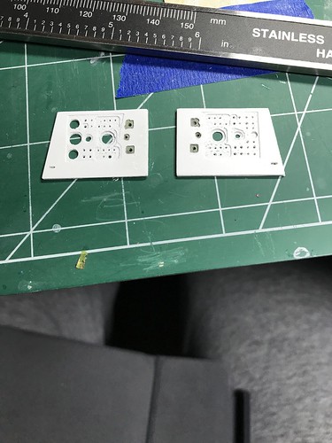
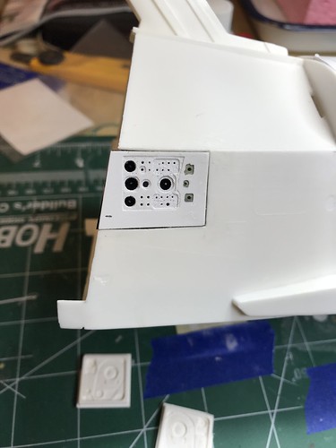
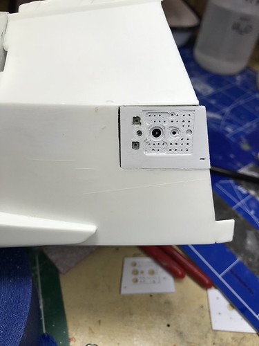
I downloaded Orbiter and looked at the game’s assets, which were fortunately stored as separate files and not compressed into one big data file. The flight deck model was actually still a Blender file, in fact. I extracted those geometries and used them as guides to draw printable 3D shapes. Since the screens, buttons, and lighted switches are texture maps, I used Illustrator to trace the texture maps, saving it as a .svg file and importing that into Blender, providing a guide to where I needed to create holes for the lighting to shine through.
Let me know if you find this approach helpful to you. I’d be happy to send you the Orbiter flight deck model (it’s open source) if you have trouble extracting that asset yourself.
-
Hey Rittic, great work on your seats!
I had tried to make the seats in my flight deck look more accurate, with the metal frame and the rods supporting the headrest, but they were way too thin for Shapeways to print in fine detail plastic.
So my seats, unlike yours, are blocky and obviously not accurate. But, as I found out once I sealed up my build, if you are building the flight deck in launch configuration with astronauts occupying all of the seats, you can't see any seat detail from any of the external windows, including the overhead ones.

I'll be very interested to see what your Form 3 can do with details that tiny. It would speak volumes if the print quality of the Form 3 outperforms that of the material jetting printing technology that Shapeways uses for fine detail plastic.
-
Thank you so much Rittic for introducing yourself and purchasing the upgrade parts. I look forward to following the progress with your build and learning from your approach; please feel free to post to this thread.
Thanks as well for the fantastic link to the German build; that’s a really clever approach using the mesh to simulate surface textures, both for the thermal blankets and the tile.
-
Hello SpacecraftGuy,
Thank you for the kind words about the parts; I’m grateful to the community that has been so encouraging and supported the project.
With regards to selling the files directly to modelers, I am not quite ready to proceed in this direction, but I will keep it in mind and consider it if this makes the most sense in the future. I hope to purchase my own resin printer in about 2-3 years and will see if the consumer level technology at that point will be sufficient to reproduce the details with these parts so that one can forego Shapeways; the Form 2 test prints of the beanie cap that FormLabs kindly made for me a few years ago were noticeably less crisp than the Shapeways fine detailed plastic printed parts. If my home printer of the future makes great parts, I may just sell the parts directly to the modelers from an online portal like HotDog and others.
Let me know if i can help answer further questions or help you plan further for your build, either here, or via the direct messaging function on ArcForms, or via Shapeways messaging.
-
Whoops, posted to wrong thread just now.
I concur with mb1k; it’s a real pleasure watching others work with these parts in their builds.
-
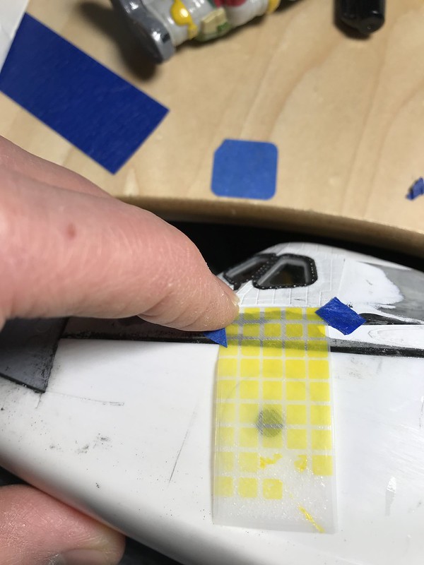
Dave (and other modelers), here is an SVG file for the paint masks for the windows and the fore RCS thruster that you can import into Cricut Design Space; good luck negotiating with your wife for Cricut usage time. I already sent you these masks in the envelope with the HUD frames, but since you have access to a digital cutter, you might find having these useful in case you need to make more paint masks.
Let us know how your attempt to fit the parts into the Revell goes.
-
Hello all, great work MedicModeler10!
Forgive me for posting this resource that I am sure most of you have already seen, but Steven Jochums did a tremendous amount of work in coming up with his thermal blanket modeling guide that he kindly shared with the shuttle modeling community here:
http://www.lakecountyspaceport.com/files/100625718.pdf
I don’t know if a laser cutter could create the quilted look on a sheet of material (i.e. the orthogonal matrix of protruding bumps with the linear border outline). HotDog might be able to give us some guidance if his thermal/tile overlay project successfully created the look of the thermal blankets in styrene with a laser cutter.
Medicmodeler10, I will follow your build thread with interest as well.
-
Thank you Pete and Medicmodeler10 for the compliments about my parts; I’m gratified that they are being received so positively by the community. Thank you to all who have purchased the parts or contributed to this thread.
Pete, thanks as well for the heads up about the large volume of sanding/filling work that awaits. My build is on pause as I try to figure out how to create the tile overlay for the rest of the model surface; HotDog’s plan has a lot of promise, and I think with a laser cutter and a thin rubber membrane, it might be possible to simulate the tile pattern over the rest of the orbiter. I bought some dental dams and they’re thin enough to blend in with the 0.1 mm raised tile pattern on the Shapeways parts. Since they’re elastic, I think they might better conform to the curved surfaces than styrene sheet. But the geometries required to make all of the elements to lie down correctly over the complex curved surfaces will take some trial and error, and I am not going to have a shop space for the next two years to run a home laser cutter/engraver to do this kind of work.
I had hoped that my Cricut Maker could engrave the tile pattern on a membrane, but for a variety of reasons, it’s not capable of creating the tile patterns on a thin sheet of material.
Hopefully putting down a thin latex membrane will smooth out/cover up some of the imperfections in the kit body and reduce the amount of sanding and puttying that are in my future. I was hoping that also simulating the thermal blankets would cover us more of said imperfections.
The other idea that came to me is to print on flexible resin:
https://all3dp.com/2/flexible-resin-3d-printing/
I don’t think this will work, in that the thickness of the overlay should be only 0.2 mm thick, but perhaps someone with a resin 3D printer can provide some guidance on whether on not one can print this thinly in this substance.
Medicmodeler, please be aware that the parts were created for the Monogram orbiter model. I am not sure how well they will fit in you try to cut apart your Revell orbiter.
-
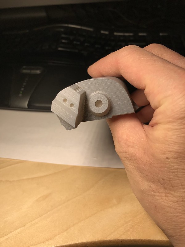
SImon, I really like how you put the microLEDs in those aft slots that I tried to shape like the fluorescent under cabinet lights. I'm looking forward to seeing how the light from those alcoves floods the aft area when it is sealed up.
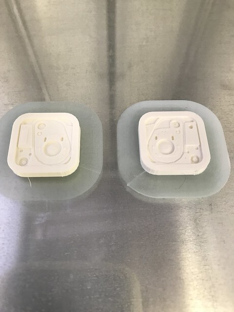
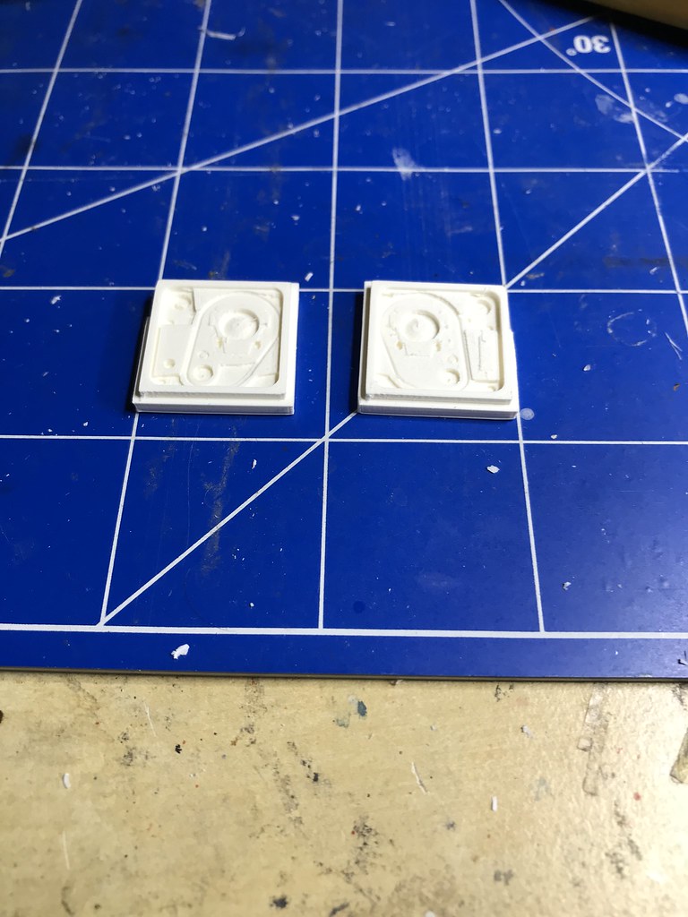
JPaunicka, I completely share your the desire to forego the Shapeways middleman and print my own parts with a resin printer. I sent off the tiled roof of my beanie cap model a few years ago for a complimentary test print by Formlabs on a Form2 to see if it could produce the parts at the quality I wanted, and the tile detail wasn't quite at the level necessary to keep pace with the Shapeways binder jetting technology used for fine detailed plastic. There are certain areas where the tiles looked crisp, but in other areas the tiles got smudged together (I think you can see the tile edges lose their definition in the area between two foremost windows). These two pieces below were printed by their technician with different orientations. I put my dream of buying my own printer on pause until the technology advanced a little more.
Obviously I'm hoping that home resin printers will continue to make improvements and I'm sure at some point I'll set up my own print shop.
Oddyssii, thanks for buying my umbilical parts on my Shapeway storefront! You're the first customer to order the newly posted parts! Here is a template to aid in locating the square cutouts in the plastic hull:
https://www.dropbox.com/s/f0cyzb3rk4ow6oj/umbilical template 2.pdf?dl=0
-
Thanks Tracy for the vote of confidence. Will try to make the T-0 panels in 1/100 for the Tamiya model.
JPaunicka, the parts are for sale now in my shop:
-
Thank you both for the kind compliments. Thanks to the trial and error learning curve of the beanie cap parts, I think these aft parts came together with less mistakes.
JPaunicka, I will be happy to put these parts up for sale on my Shapeways storefront. I need to get the depth of the backstop ridge adjusted (it’s part of the T-0 umbilical base piece), and then I will post the parts for sale, probably this weekend.
I apologize in advance to modelers interested in buying the parts. They will not be cheap, and that’s not because of my profit margin; it’s really set by Shapeways. At some point, I’ll have my own SLA printer and can produce these directly, but that’s a few years off.
-
Simon, your lighting effects look great! Much more sophisticated than my effort. I look forward to seeing the topside image so I can better appreciate your approach using the microLEDs instead of the SMD LEDs I used.
My Shapeways prints finally arrived.
I primed them for better visibility of the surface details.
The slightly undulating texture of the quilted-appearing asbestos insulating rings actually comes across in real life, not so much with the light reflections in this photo. I'll try to highlight the simulated rivets here (the little dimples) with a white/gray pencil like I did on the beanie cap window bolts. That should provide a nice contrast to break up the scale black monotony of the tiles.

Here is the image I used to try to come up with the asbestos rings and the rivet pattern for comparison.
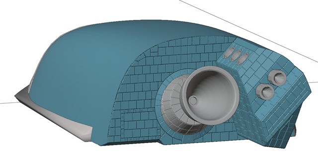
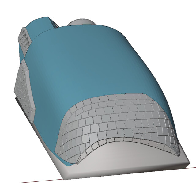
Here is the underside tile pattern to the body flap.
And here is the top side. You can tell that the print layer line artifact affected the sloped top side during the print, but it's not too noticeable, especially after it is partially hidden by the SSMEs.

I'm relieved to find that the OMS pods fit in their mildly asymmetrical spaces, and the tile design blends at the line where it merges with the rear of the payload bay bulkhead.
The lateral tile protrusions on the OMS pods:

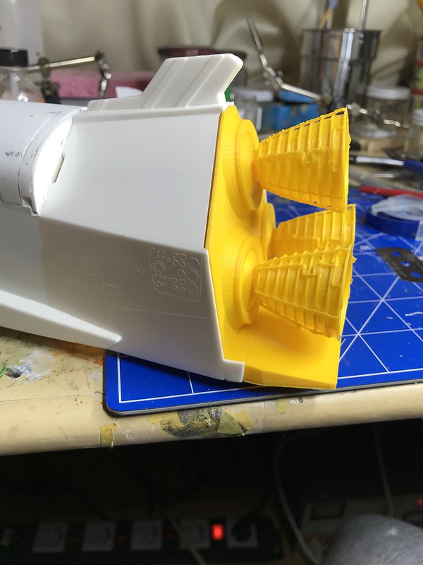
The ribbed interiors of the SSME's:
I need to make some adjustments to the raised ridge I glued inside the fuselage here to backstop the SSME mounting plate so that the part seats a little more deeply, but it shouldn't require too much work.
It's a little fragile not glued together, but the parts appear to fit okay.

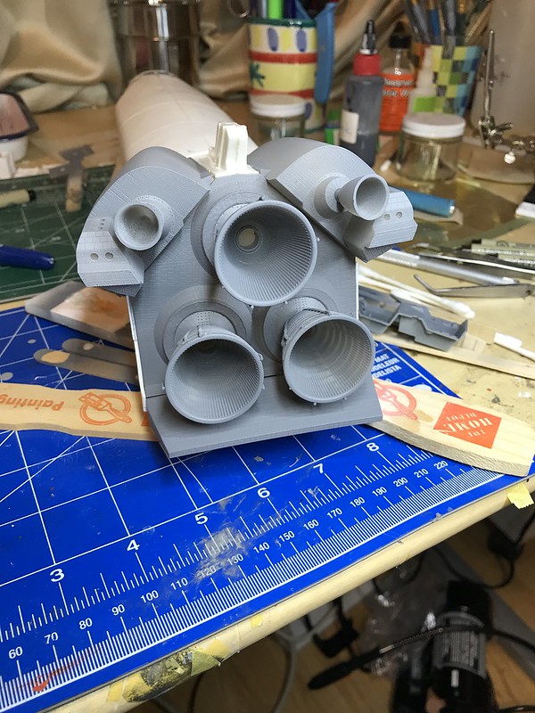
I still have to put these tiny aft RCS nozzles (red rectangle) into their sockets, but it shouldn't be too difficult. I left them as separate parts so I could paint this little tan stripe on them (blue arrow):
Here is some of the tile detail on the aft RCS thruster/aft OMS assembly:
These underside faces of the OMS pods are exposed once assembled, so I tried to model the tiles on them as best I could from the limited photos I found. However, once assembled I doubt that one will be able to see them, since they'll be obstructed by the other structures like the engine nozzles.
Some of these surfaces might require a little sanding cleanup where the print surface came out a little rougher, but for the most part the details appear crisp.
-
Thank you Simon. I sent off the parts to Shapeways, and should receive them sometime in the second half of February.
In the meantime, I went back to work trying to finish the underside umbilical doors.
From this reference:
https://core.ac.uk/download/pdf/10543663.pdf
I tried to recreate some of the door drive mechanism and the uplatch hooks, trying to figure out how the linkage arms would look with the doors in the wide open position. The sizes of these protrusions are tiny, on the order of a millimeter or two.
I ran a test print, but because of the overhanging linkages, I used dissolvable PVA s a support material; those linkages are only a millimeter wide. They should probably be thinner, but I don't think they would be strong enough structurally to work.
The good news is that the doors seem to fit into the spaces on the orbiter with some room to spare.

You can see in this image above the roughened surfaces where the PVA was printed on top of the PLA, resulting in a less smooth finish.
I just found this image now which shows the linkages with the doors in the fully open position, and they actually don't protrude in the way that I modeled them. Since they protrude only to the level of the door surface, this will greatly simplify the geometries involved in printing them. I'll try to refine the design a bit to approximate the mechanism a little more accurately. That thin linkage arm I'll try to simulate with some wire.
-
I didn't like some of the imprecisions in the last T-0 prints, so I made some modifications and tried again.
The bevel that helps to center the drill for the wire holes in these ports is now on the inside of the port itself, which results in a better centered wire. On the prior versions of this piece, the centering bevel was on the other side of the hole facing into the interior of the fuselage, and my drill attempts weren't as vertical as I hoped, so the wire emerged into the port off-center.
Furthermore, the base pieces of the T-0 umbilicals weren't seating as precisely as I needed thanks to the sloped edge that slid underneath the OMS pod above it; the base didn't "click" into place in one specific position; there was too much play in its placement. So I created a little jig to try to seat the base more precisely. In the next image, the jig is the white piece, and the black piece is the base.

Now the jig fits into the space that will occupied by the outward facing beauty piece, and its depth is consistent throughout thanks to the flange that rests against the orbiter hull around the cutout.

As a result of the jig providing this surface, the base rests at a more consistent depth in its position, and the imprecision of the sloped edge underneath the future OMS pods interface doesn't mess with the alignment as much.

Now it came time to sand down the outward face of the beauty pieces to avoid a step between them and the surrounding fuselage. This helped to remove some of the irregularities of the FDM printing process, but only on the most superficial layer.
After priming, I applied some latex mask around the fore recessed areas that are supposed to be a greenish-gray:

Those received a spray coat of the green-gray color, which thanks to iModelKit turned out to be 2 parts Model Master RAF Interior Green, 1 part Model Master Euro 1 Gray.
Here is a photo I took of Discovery at the Air and Space Annex that I used as a color reference for iModelKit.
Here they are, temporarily glued into position to confirm depth and placement. They are about the right thickness, so with a little putty there shouldn't be a visible step off.
You can see in the last image that the artifact from the FDM printing process leaves a surface that isn't really smooth under magnification. The most superficial perimeter surface is smooth thanks to the sanding, but the recessed details show the defects from the printing. If I sent these off to Shapeways and printed them in fine detail plastic, they should look smoother, but I'm undecided if I want to send even more of my income to Shapeways.
I have been tweaking the OMS pods a little bit to get them to fit the spaces more precisely. After one more set of test prints this week I should be ready to send all the parts off to Shapeways for what is looking like a very expensive print job: OMS pods, body flap, SSME mounting place, SSME nozzles. It takes 17 hours to print one OMS pod at the highest resolution on the Ultimaker, so each time I revise the model it takes a few days to produce new prototype prints.

-
Hi Simon,
Here is how I post from Flickr to ARC Forums.
I select the photo on Flickr I wish to post, then click on the share icon. That brings up this dialogue box, and I copy the URL in the window to the clipboard. You need the URL from the "Embed" tab. The "Share" tab URL won't work.
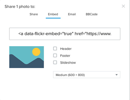
Then, when on ARC forums, I select "insert image from URL" from the "other media" dropdown menu on the bottom right of the text box where you are composing your post.

Paste your link into the dialogue box that follows.

In the middle of that pasted link, you will find a shorter embedded URL in quotes that is identified as "img src."

This is the link you wish to insert in the ARC forums URL box, starting with https: (no quotes), ending with .jpg (no quotes). You can delete the rest of the text.
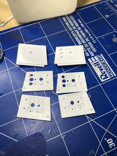
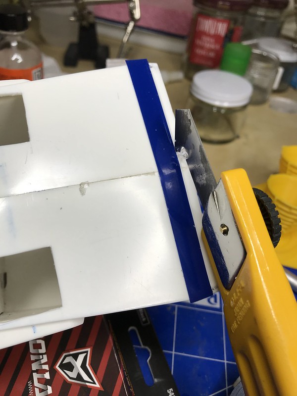
Here is my attempt to create the T-0 umbilicals. Here are the pieces from the Ultimaker with the edges sanded to free them from the support material.
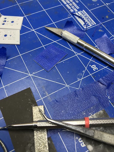
I need to create an accurate mask around which to cut out the existing kit plastic, so I taped one of the outward facing pieces to some painter's tape, then trimmed the excess edges of the tape off with a blade.

I used that tape polygon as a guide for making my cuts on the fuselage.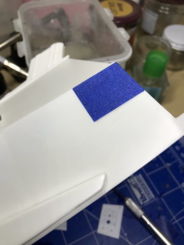
I then placed some labeling tape against the boundaries of this piece to constrain my scribing tool.
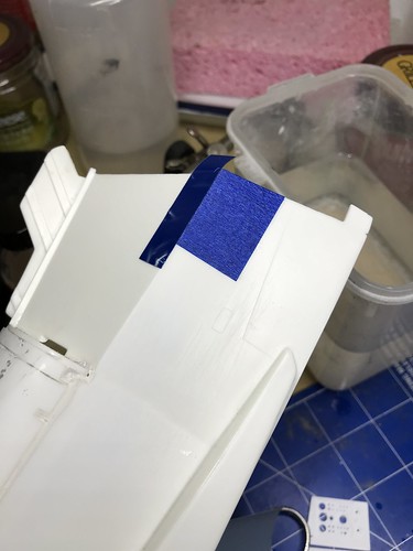

Then I scribed in the perimeter of this cutout with the carbide tip scriber.

Once I had a reliable perimeter scribed into the plastic, then I used the Olfa plastic cutter to remove most of the plastic.
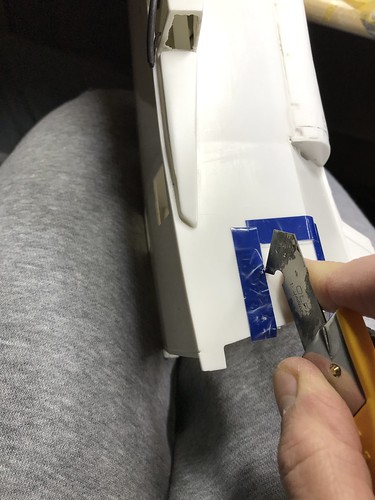
As I found out (oops), the Olfa blade has a sidedness to it. So, to avoid cutting through the labeling tape, I needed to keep the left side of the blade against the tape (in the direction you see in the image above). Consequently, I had to turn the fuselage around to cut the other side. You can probably guess how I made this discovery.
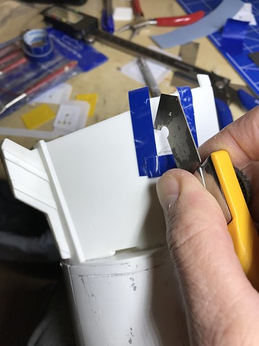
I then used the MicroMark toothed razor blades to finish the cut.
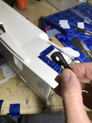

I dry fit the recessed part of the piece into the hole, and noted I needed to do a little sanding to get the piece to seat correctly. I marked the corner with a black sharpie where I needed to remove a little more plastic.

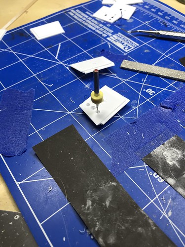
I drilled some 0.5 mm holes in the approximate center of these simulated ports, and then painted the outward facing portion with black primer.
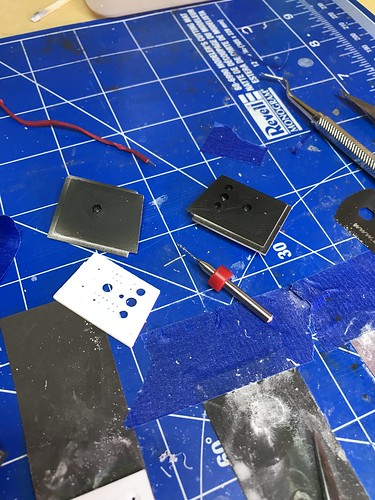
After drilling, I cut short sections of silver-colored wire (monofilament) to simulate the cylindrical projection that sits in these ports (I think they are for LO2 and LH2). I then used the glue gun to secure them from the backside.


I then placed these pieces in the slots and secured them with the glue gun.
Here is the starboard piece from the outward facing side. I messed up the paint job when some of the glue leaked and smeared over this face, so I had to scrape it off once the glue dried. Fortunately, I don't think you'll be able to notice the amateurish paint job once the other piece is placed over it.

Here I've dry fit the overlying pieces to confirm that they will fit. They are thicker than needed, so they stand off from the surface. This is because as an artifact of the 3d FDM printing, the surface that is produced isn't smooth enough; you can see the irregularities of the deposition process. So, I will need to sand it down until it lies flush with the adjoining plastic, but then the top layer will look smooth enough to blend. The irregularities in the deeper recessed surfaces hopefully won't be too noticeable.

Sanding them flush and then test painting them will be the project for the holiday weekend.
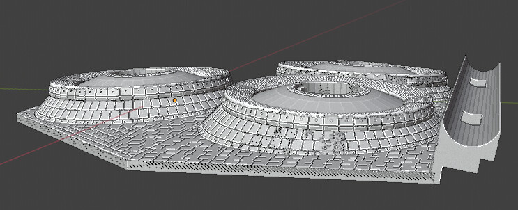
I gave up for the time being on trying to create some sort of tile sheet on the 3d printer that I could stick on the body flap, and just drew the tiles into the 3d printed piece. Here are some images from Blender. I'll try to print it at work tomorrow on the Ultimaker, but it will likely be another ridiculously overpriced upgraded part for my build printed by Shapeways in fine detailed plastic. These aft parts for the model are costing more than the beanie cap parts. Up to this point, it looks like the only parts where the Ultimaker's quality is adequate for the task are the T-0 and belly umbilicals, with their relatively simple layered details and lack of sloping surfaces that would show stair stepping at Ultimaker layer height resolution. The inability to print smooth sloping surfaces is one reason why the body flap won't look good enough printed on the FDM printer.

-
Thank you Simon for the compliment and for purchasing the parts. I hope that they make the build more enjoyable for you. I'm sorry about the expense; the Shapeways fees comprise the bulk of the cost of these models. I think I make enough from the parts sales to cover the cost of purchasing my own parts from them.
I did a quick search for the OMS pods on Shapeways and didn't come up with any hits. Would you please forward me a link to the OMS pods you found so I can see how another modeler made them?
Hotdog, I forgot that you had already made the T-0 umbilicals. Thanks for mentioning them here; I have printed out one prototype of my T-0 umbilicals and have to make some modifications, so I'll print them again this week and see if they will be usable, and if not, I'll be ordering yours.
Not to pester you with the question on everyone's mind, Hotdog, but is the 1/72 tile set stuck in development? Is there something we can do on our end to help you surmount any challenges? I was thinking of trying to make it in 0.2 mm thick silicone sheet vie styrene so that it conformed better to the curved surfaces, but I'll need a laser cutter like you have access to in order to do it. My Cricut digital cutter can't handle files that big.
-
Thank you Pete for the encouragement. I'm sticking with the launch build for now, and I already assembled the ET and SRBs OOB several years ago before I learned how to create replacement parts using 3d printing and design. Consequently, for now I'm not planning on building more accurate parts for those components. However, maybe after I finish the Discovery and display it, I might be tempted to follow Manfred's inspiring work and try to imitate his brilliant ET and SRB corrections at the much less difficult 1/72 scale. Given how expensive Shapeways is turning out to be, this might have to wait until I'm retired in a few years and have my own resin printer (I uploaded just the OMS pods into Shapeways and it will cost a litel over $100 to print the two of them with the nozzles in fine detailed plastic). My job places me overseas, so I don't have a dedicated shop presently, just a hobby room in an apartment.
I've been working on the T-0 umbilicals recently. I used these diagrams from George's Rockets.
http://georgesrockets.com/GRP/AOL/NARshuttle/Scale_Details.htm
Here is the port side:
And the starboard side.
I'll test them out on the Ultimaker this week and see if they will fit well and not be too difficult to blend into the existing plastic.
-
Hello Simon and Tracy, thank you both for the encouragement. Tracy, I'm awaiting your response to another message in your Arcforums inbox to help me figure out how to get the umbilicals to fit the Tamiya model. Scaling those parts down shouldn't be too hard.
Simon, I would be delighted if you would share with us how your build is progressing; please feel free to post to this thread with images of your progress so I can better understand how others are using these part on their models. Thank you as well for purchasing my parts.
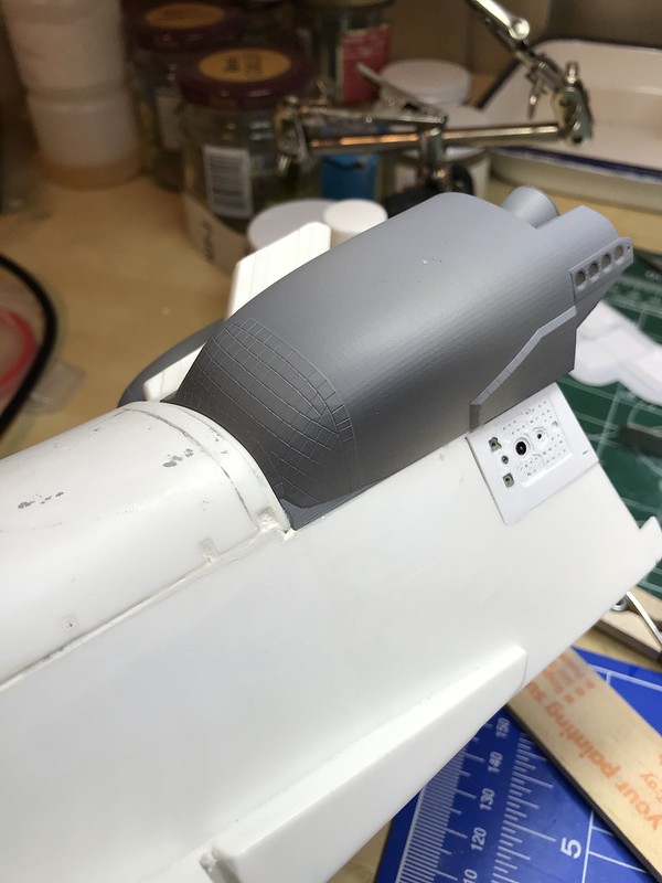
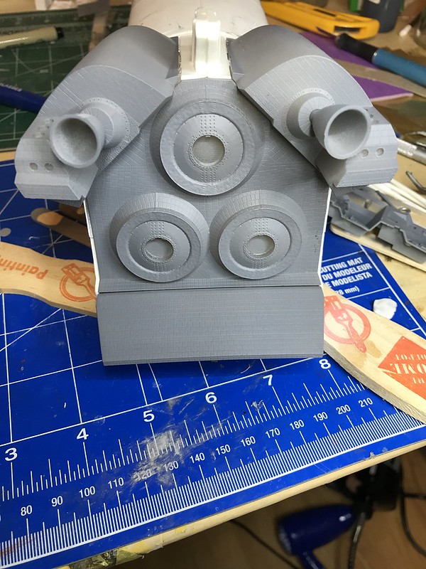
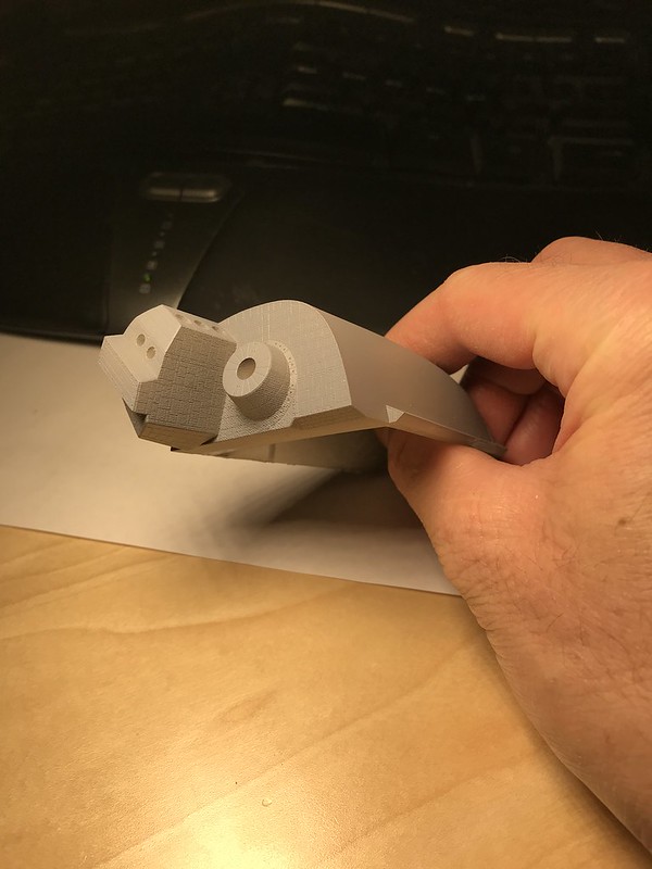
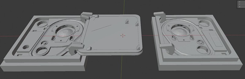
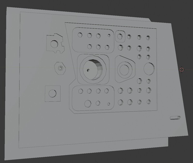
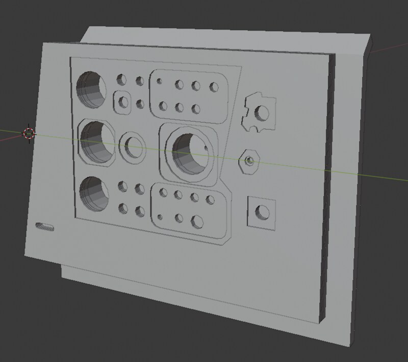
I have tried to modify my SSME mounting plate so that its interface with the body flap looks more accurate. I had thought that I could leave the bottom lip of the fuselage intact, but after realizing that the body flap has this semicircular surface where it articulates, I decided to make my mounting piece full thickness here and thus require a little more surgery.
Here are the current versions of the parts in Blender. I added some alignment keys both for the body flap and as you can see in the sockets of the SSME mounts. I went to the Air and Space museum annex in Virginia a few years ago to take pictures of the Discovery, and as it turns out, the superior and starboard SSME nozzles are identical, and the port nozzle has a different arrangement of the pipes.
This image shows how I am going to try to get the SSME mounting plate to integrate with the fuselage inferiorly along this recessed lip. You can see that if I had left the inferior edge of the fuselage intact, there's no way I could have sanded it down accurately enough to match the semicircular curve needed for the body flap hinge.
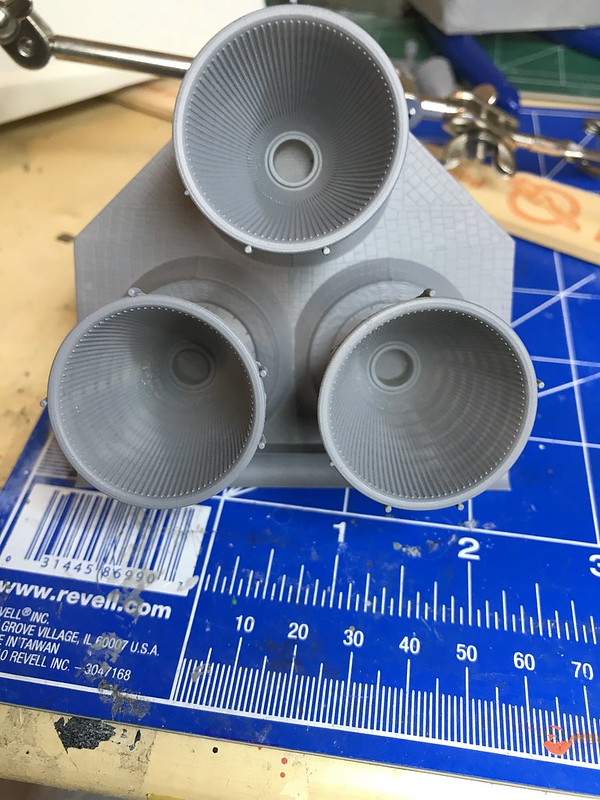
The rounded internal ribbing on the SSME nozzles are 0.17 mm tall and about 0.5 mm wide at their base. Hopefully they will look realistic when printed in smooth fine detail plastic. The Ultimaker can't reproduce these details at this size, especially in the print orientation I'll be using to test out the prototypes.

In this image it's easier to appreciate how the piping arrangement for the superior and starboard nozzles differs from the port nozzle.

One of the nicer features in Blender 2.8 is the ability to display reference images in the actual 3d space, using the Wayback document archive that Habu2 linked to earlier. Here is my attempt to get the body flap shape accurate enough for the model part, using PNG cropped bitmaps from those vector graphics pdf files.
I haven't yet added the tile pattern to the body flap. I mention this further below. But, if I want to embed the tiles in the printed part, I might have to break up the body flap into upper, lower, and side face pieces, since the best resolution for fine details is quite print orientation dependent.
The inferior lip of the body flap interface required me to do a little more surgery on the fuselage, removing a 3.8 mm width strip, leaving the lateral walls intact. I want to be able to simulate this tiled body flap hinge point afterwards, so I'll need some of the plastic from the fuselage to overlap the body flap semicircular section.

Here is the section to be removed.
I used the carbide scriber and some labeling tape to create a score line, for the Olfa plastic cutter to follow.
Here is the result of the surgery.

Here is the mounting plate now in place.
And the underside:
Here is the prototype of the body flap:

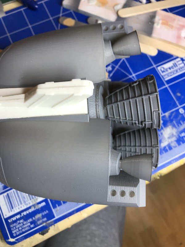
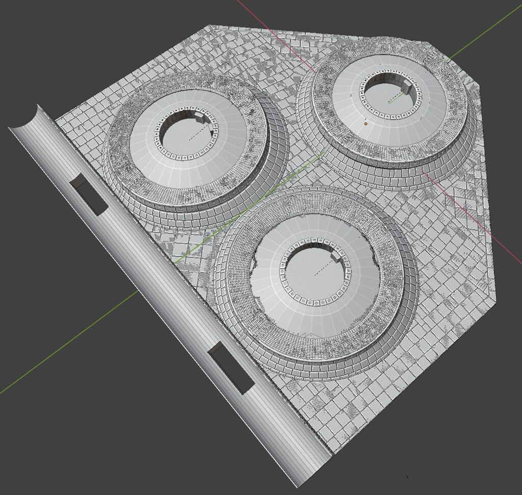
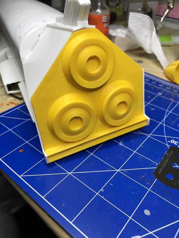
Here are the nozzles, with their keyed insertion collars.
There's a bit too much play between the collars (10.7 mm wide) and the sockets (11 mm), so I might tighten up the clearances before I send these off to Shapeways.
I also need to figure out how to simulate the T-0 umbilical panels; hopefully I can just print out some pieces on the Ultimaker that will suffice like with the external tank umbilicals. I can see that the T-0 umbilical pieces will need to accommodate the SSME mounting plate in that tight aft corner.
I am also struggling to figure out how to reproduce the tiles on the rest of the orbiter so that it will match, more or less, the tiled sections on these various Shapeways-printed pieces. The tiles on these parts have about a 0.2mm gap between their edges, and they have a depth of 0.1 mm. I thought about using the Cricut to score 0.1 mm thick styrene sheet, but I am not sure that it will conform well to the underlying curved surfaces. I also thought about using thin silicone sheeting scored with the Cricut; the silicone sheeting would be far more flexible and could be stretched to conform better to curved surfaces. The Cricut allows you to create custom pressures for the blade, so I am guessing that I could through trial and error find the right pressure for the material so that it scores but doesn't go all the way through.
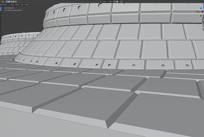
But I'm worried that scoring any sheeting, styrene or silicone, will look too obviously different than the tiling surfaces stemming from 3d printing. I use the "inset" function in Blender to simulate the tiles; this results in a distinctly triangular gap reminiscent of chocolate bars that looks like this up close:
So, I started playing with the Ultimaker again. The Ultimaker 3 has dual print heads, which are usually the most useful when using PVA as a dissolvable support material. But I tried experimenting to see if I could create discrete 0.2mm thick or more tiles in PLA, then coat the backside with a 0.1 mm layer of TPU 95a, which is a nice rubbery material that is pretty strong.
After a couple of really unsuitable attempts, I printed these two yesterday.
In this first one, I adjusted the delta between the two print heads so that the white TPU layer printed far above the yellow PLA layer, which was squashed against the printer bed. By squashing the outward facing layer against the print bed, it fuses the linear deposition artifact created by the extruder and looks far more uniform and smooth. While the print model is supposed to be 0.27 mm thick for the PLA layer, then another 0.1mm added for the TPU extruded on top of it, but according to my micrometer, this print is 0.77 mm thick.

In the next print, the delta was much closer to zero. As you can see, the TPU layer is more fused with the PLA layer, so much so that it filled in the spaces between the tiles too much; again, while it should be 0.27+0.1 mm thick, the micrometer for this reads 0.15 mm total, since the TPU fused with the PLA layers (the TPU nozzle temp is higher than the PLA temp by about 20 degrees, so the TPU melts the PLA a little when it gets laid down over it). But the membrane that it produced is far more promising for the purposes of covering the orbiter than the first test.

The tiles on the right side of the print have a little Z axis definition against the TPU seeping in from the back. I will try to narrow the space between the PLA tiles to see if I can keep the TPU from obliterating the gap and mess with the delta a bit more.
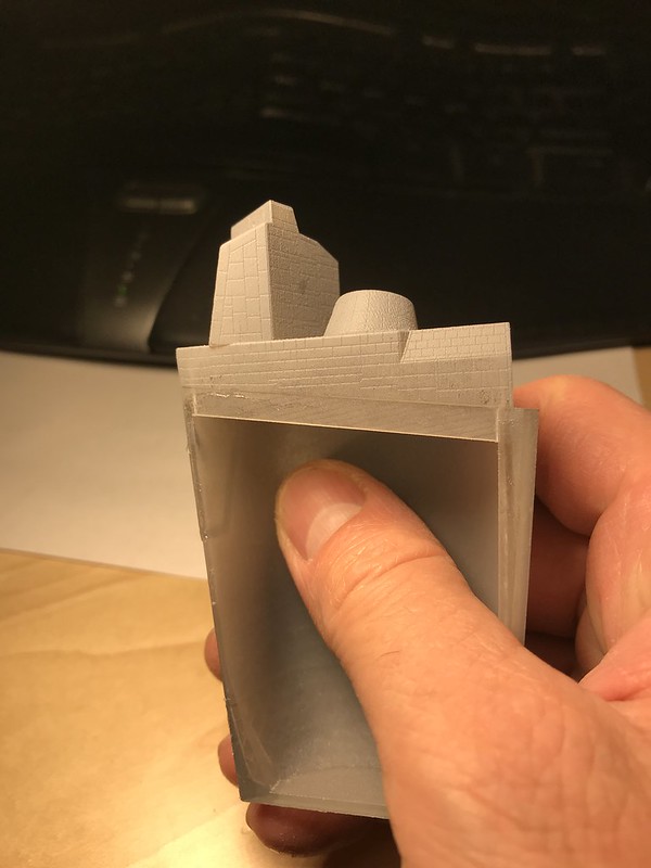
The good news is that I think the membrane is thin enough that I have some more room to thicken the PLA layer, which will hopefully give me enough standoff to keep the TPU from destroyed the tile gaps. Here is the membrane pressed against the beanie cap for comparison. I don't think you can tell from the photo, but the 0.15 mm thick print is clearly thinner than the beanie cap tiles.
Ideas from the field would be welcome at times like this. Hotdog, if your tile kit is moving forward, I would much rather use what you have done than try to reinvent the wheel here.
-
I have tried to create parts to simulate the ports on the underside of the shuttle that connect to the external tank LH2 and LO2 umbilicals.
I used the images in this document as my main reference:
https://core.ac.uk/download/pdf/10543663.pdf
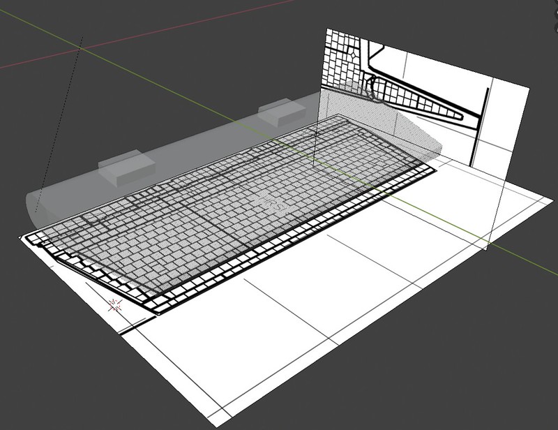
Also, when I used the excellent reference documents that Habu2 linked to above, scaling the diagrams to 1/72 results in a door dimension edge length of approximately 19 mm, but that turns out to be too large for the width of the space on the Monogram model; with the doors in the open position their inner edges would overlap (i.e you would need 19 mm x 4 = 76 mm width to accommodate them, and there isn't enough space to do that without some messy cutting through the side walls of the orbiter central hull section). So I fudged the door edge lengths to 17 mm and moved them a little inboard so that their edges don't collide with the edge of the hull.
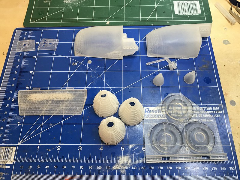
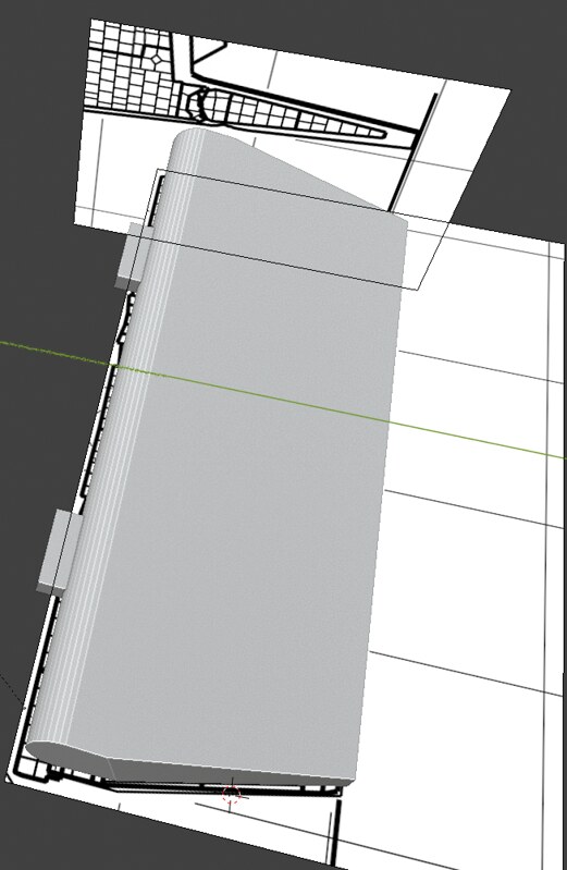
Here are my 3d modeled parts so far.

Here was a test printout on the Ultimaker before I squared off the edges. Surprisingly, the quality didn't differ perceptibly to my eye between printing with the 0.4 mm nozzle and the 0.25 mm nozzle.
Here I tried to mark the areas where I would need to perform the cutout, attempting to get proper alignment of the ET LO2 and LH2 umbilicals. Manfred's work on his LH2 and LO2 umbilicals really puts my efforts to shame here. I also wish I had seen his trick with the flour and ribbing to simulate the insulation foam before I did my build.

Here are the parts with the squared edges to make it easier for me to get them to mount.
Here they are dry fitted into the hull.

I'm not sure anyone else will notice, but the alignment of the LO2 and LH2 umbilicals into their respective ports on the parts looks close enough.

I will work on modeling the umbilical doors, but that shouldn't be too difficult.
I'm pleased to find that the quality of the Ultimaker prints for parts like these that are geometrically simple for an FDM printer (i.e. no supporting lattice, no sloping surfaces which would show the layer lines) will suffice, and I won't need to send these off to Shapeways for printing in fine detail plastic. Surprisingly, with the 0.4 mm nozzle you end up with details that are superior to what you would get with injection molded kit parts. However, for the OMS pods, you can really see the artifacts of the printing much more readily.
-
Awesome, thank you so much Habu2, this is fantastically helpful.
-
Hello all,
So after some sanding and filling, I think I have the cargo bay doors adequately positioned. As luck would have it, it's not the border between the beanie cap and the bay doors that has a step off, but actually the aft edge of the bay doors and the start of the OMS pods that doesn't fit correctly.
The slight step off here I tried to address with some shims. This will all be underneath some thermal quilts, so I think I can get away with this level of crude approximation of the interface.

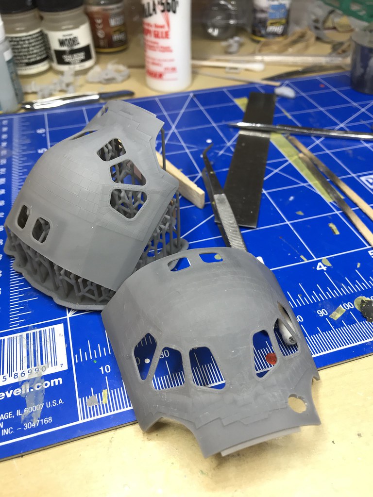
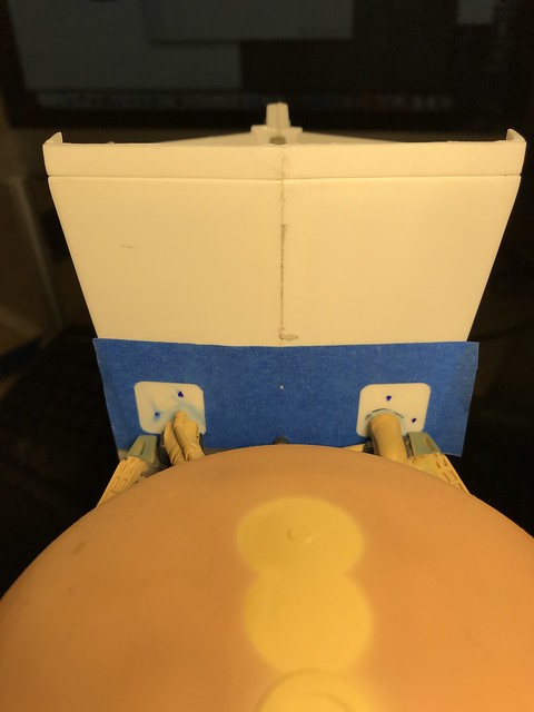
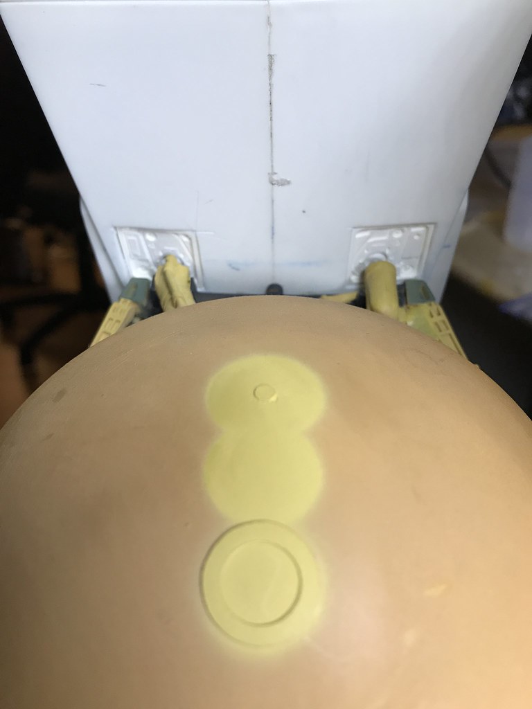
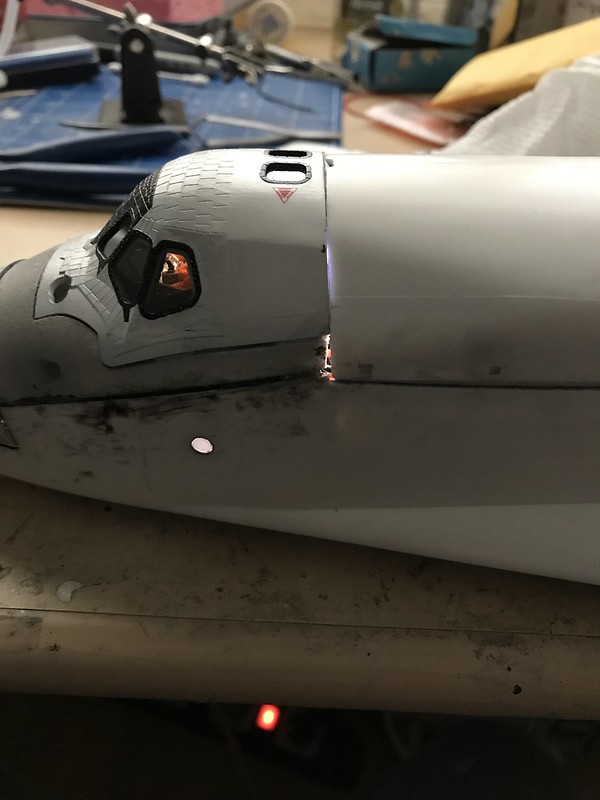
My heart stopped when I lit it up and had a huge light leak where the aft wall of the flight deck separated from the curved ceiling. Argh.
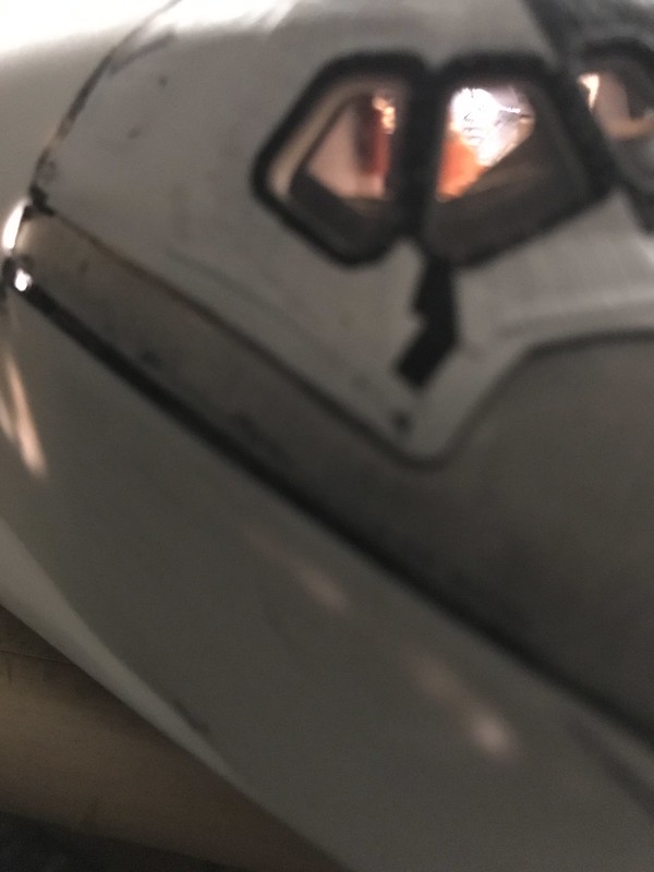
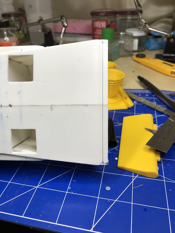
After ruminating on it, I realized that I couldn't leave this one unaddressed, so I cringed as I proceeded with some pretty drastic surgery. I was not sure if I was going to be able to make this look pretty when it was all over.

If you look closely, you can see where the pieces separated.

I resealed the join with some CA mixed with metal pigment, and the squirted some glue gun glue into the hollow space between the ceiling part of the flight deck and the shell of the beanie cap in the hope that that would keep the join from splitting open again.

One more round of CA mixed with metal pigment to seal it back up, then sanded down the excess.
Miracle of miracles, it actually maintained correct alignment and sealed up without a lot of trouble or step-offs.

As I mentioned above, the real fit issue was at the aft edge of the cargo bay doors. I'm not sure if this is my poor alignment when I glued the bay doors in place or bad design by Monogram.
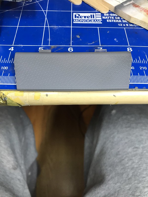
So, I tried to approximate the curve with successive layers of strips of 0.13 mm thick styrene sheeting.


After some sanding:

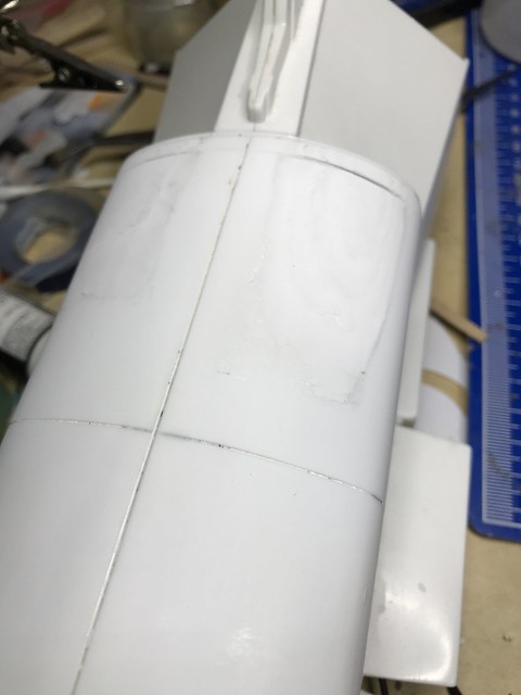
It's not quite smooth enough yet (there are some pits and bubbles in the sheet styrene where I think it didn't complete weld to the styrene underneath it, but I think I'll leave it in this state for now and try to finish it more precisely once I'm at the priming stage and can visualize more easily the degree to which the defects need to be corrected.
I then resumed work in Blender on designing the replacement OMS pods and SSME mounting assembly parts.

While the OMS pods look symmetrical here, their bases are different enough that I had to do a bit of fudging and approximation to get them to seat correctly.

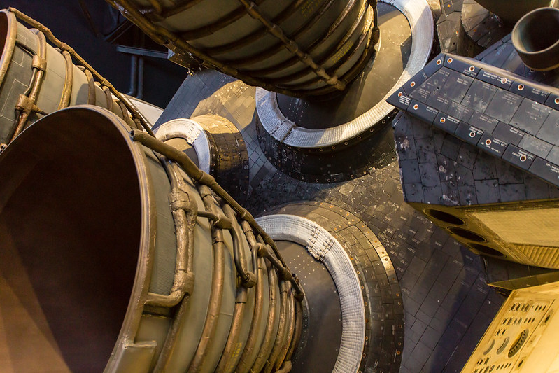
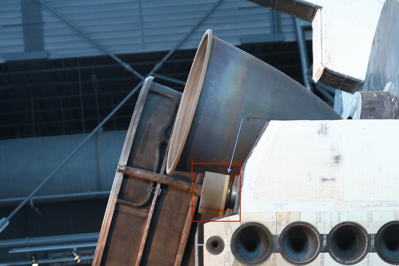
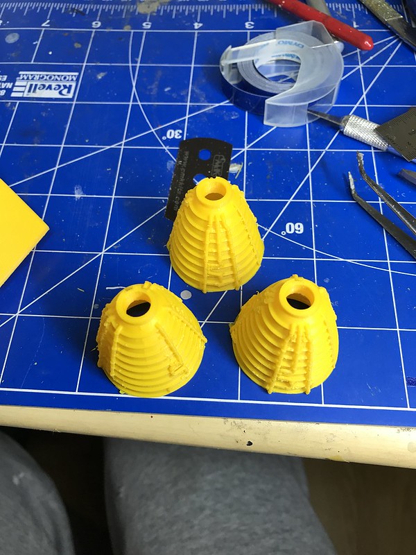
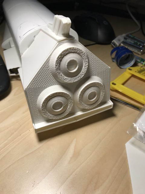
Here is my progress on the SSME nozzle mounting assembly (I am unsure of the correct terminology for these components, so if someone knows better, please feel free to correct me). I'm not sure that the resolution of the fine detailed plastic print will be high enough to capture the textured, quilted surface on the SSME nozzle insulation rings that I was trying to simulate.

Here is a close up of one of the insulation rings. Each one of those little quilted bumps in the insulation is about 0.4 mm wide.

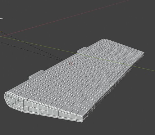
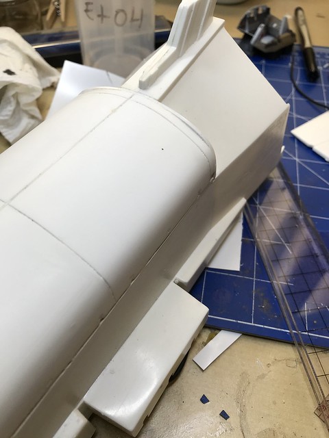
It looks like these parts printed in fine detail plastic will be expensive via Shapeways (like $60 for the mounting assembly alone). I have some more work to do to confirm the fit using the Ultimaker I have access to at work. The body flap part in the Monogram model is shaped incorrectly - the kit part is shaped like a V where it connects to the main shuttle body. The real flap is a rectangular with flat surfaces, so this may require some more surgery and creation of a replacement body flap completely

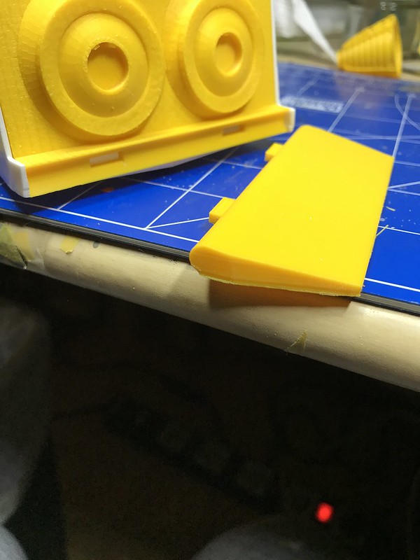
Here I took off the angled aft edge of the body to better simulate the real shuttle body flap interface. In the background are some test prints of the OMS pods.
I glued in some thin styrene strips to provide a backstop to my replacement for the SSME mounting assembly.
Here is a dry fitted test print of an earlier version of the SSME mounting assembly in place. You can see how the artifact from the layer lines of the Ultimaker at this resolution render the part unusable. This was printed with the 0.25 mm nozzle at a 0.1 mm layer height. While I thought I might be able to get away with using these prints instead of sending off my paycheck to Shapeways, I think I'm going to have to bite the bullet and pay for the higher quality prints.
In trying to come up with the body flap tiling pattern I've been looking for a high resolution version of this document that I found here that are from the Shuttle Operational Data Book, which doesn't appear to be available online in its entirety anymore:

Does anyone have this document that they would be willing to share?
I have some of the other images from this series of external finish/external insulation from the data book in pdf format:
https://www.dropbox.com/s/xzxkn8o37zsntlr/2-2c.pdf?dl=0
https://www.dropbox.com/s/mcayl5z40zep8si/2-3c.pdf?dl=0
https://www.dropbox.com/s/2032vwrjr7ijabk/2-4c.pdf?dl=0
-
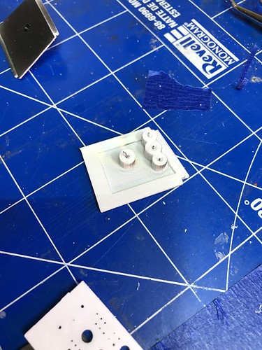
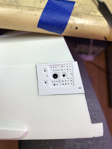
Okay, I finally received the Li-ion batter, the AA-sized battery holder, and pushbutton switches for the project.
While a AA-sized battery seems to fit easily in the wheel well, I didn't calculate the extra volume of the battery holder.
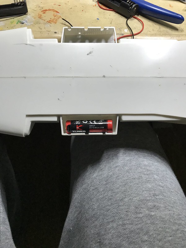
To keep the height of the holder within the size constraints of the space, I would need to mount it sideways, partially in the main fuselage space.

Furthermore, the battery holder had these little retention wings that would make it difficult to pop the battery in and out from this angle, so I trimmed those off.

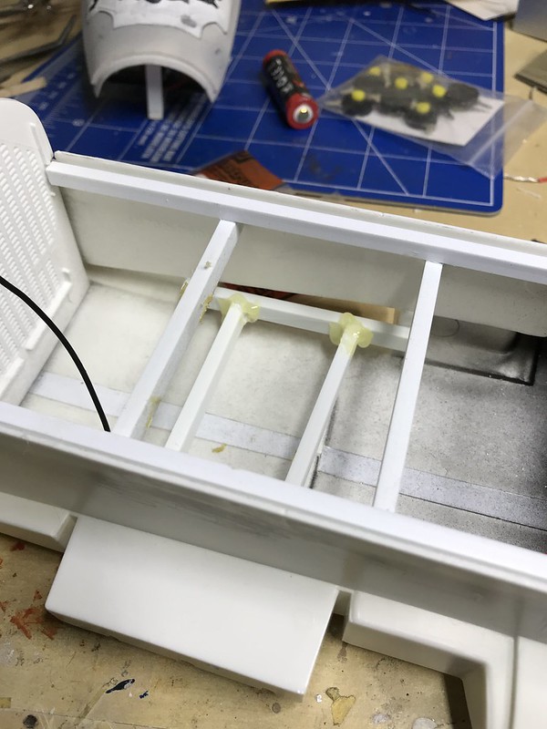
To secure the holder in place, I had to build a little backstop for it.
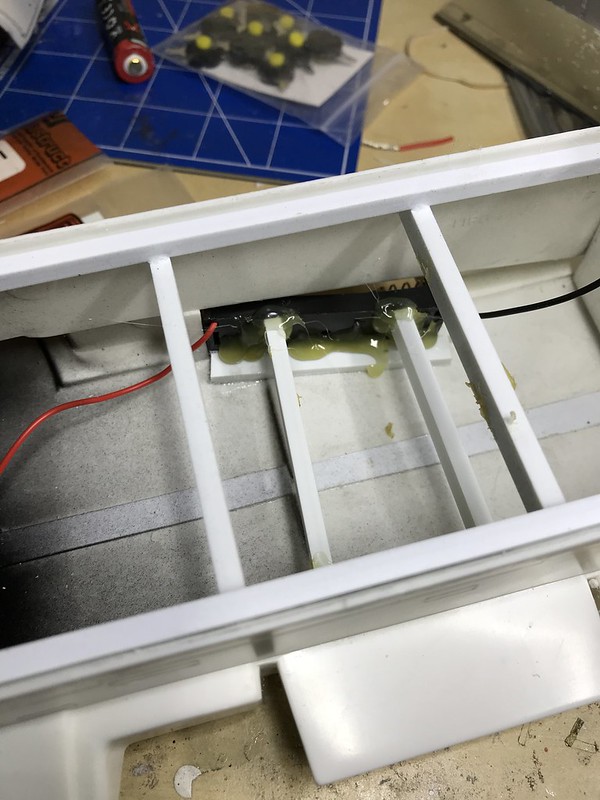
The crossbar bracing on the port side of the fuselage look like this.
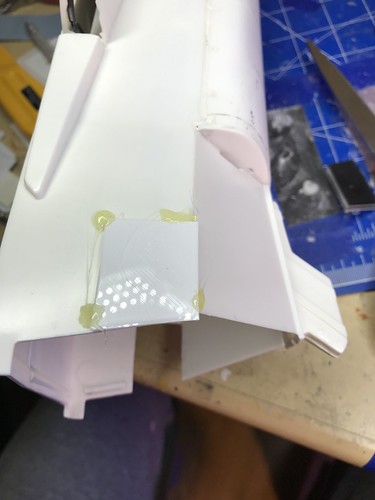
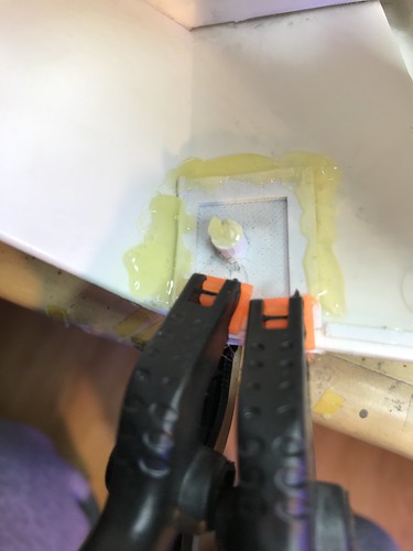
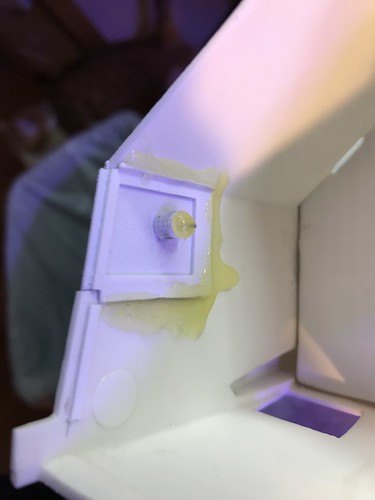
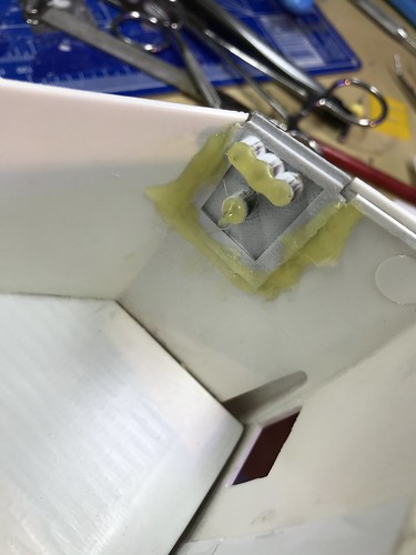
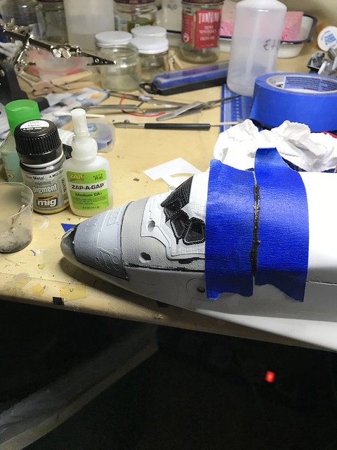
I tried a few types of glues to secure the beanie cap in place, but couldn't really get the results I wanted with CA or the glue gun. Finally, I masked off the edges to prevent spillover and used 5 minute epoxy. I dry fitted the payload bay door assembly into place to confirm that it would fit.

I plugged the circuit parameters into V=IR with 9 LEDs in parallel and 4.1 volts produced by a fully charged 14500 Li-ion battery, and came up with a resistor around 8 ohms, but when I tried it in real life it was way too weak. The right resistor for this circuit turned out to be around 82 ohms. Fortunately, the circuit and the switch worked and I didn't inadvertently burn out any LEDs when I was testing various resistors. I threaded the switch into the port wheel well but didn't secure it in yet.
I put some Blu Tack in this light gap space before closing it up.

I adjusted the payload bay door assembly to minimize the step off fore and aft, and glued it in place with Plastic Weld.
There are two step offs that will need attention, but they are both going to be underneath the AFRSI thermal blankets, so I think it won't be too hard to disguise with some thin shims on the beanie cap side of the gap to match the step.


I then mixed up some CA and Mig gunmetal pigment and tried to seal some of the gaps. While the CA was setting, I tried to adjust the joint between the beanie cap and the payload door fore edge to minimize any further step offs before it dried completely.


Finally, while that was drying, I used some Vallejo acrylic putty to fill in rest of the gaps at the payload door hinged area. This area will also be covered with AFRSI quilts and hinges, so it's really not critical to make it look flat, either.

space shuttle stack accurate flight deck question
in Real Space Modeling
Posted
That looks fantastic, Rostko, great job with the lighting!
I'm impressed as well with your discipline in creating and placing decals on all of the tiles. How did you print opaque gray lettering decals for the black tiles?