


Aurora Mark
-
Content Count
483 -
Joined
-
Last visited
Content Type
Profiles
Forums
Calendar
Posts posted by Aurora Mark
-
-
Thank you kindly Ikon!
No pictures for tonights work simply because I lost track of time and need to get some sleep rather than editing the pictures and posting them up. That being said though quite a bit of progress has been made with both the cockpit and planning future steps.
This model will most certainly have more challenges in future steps. While going over reference pictures of the Viper there are certain things that have come to light. The cut outs in the fuselage as well around the engines for example. Areas that offer a lot of detail to the eye that will really give a kit some depth, but will need some work first. But rather than leaving me frustrated I took a different approach.
Is this kit a lost cause? Is the kit unbuilable? Is it a waste of money, time and effort?
Outright "NO!" to all those questions. And I want to make sure that I make that clear. This kit is a scratch builders dream while also being a good all around kit for everyone who finds interest in the subject.
The engineering and approach to construction is very unique. There are the traditional large piece assemblies (e.g. wing and fuselage halves). But the assembly of sliding parts together and relying on the previous step to slide and lock the next parts on without a single guide pin (after the fuselage is glued together) makes this a fun approach. A lot of thought went into designing this kit. Sure it could have been made like a traditional Tamiya or Hasagawa kit with many intricate parts, but then this wouldn't be a straight forward and cost effective kit. Everything can be made more complicated for the sake of detail, but I don't think that is what Moebius was going for.
A lot of effort is going into making this build a very specific Viper. I used words like "errors" or "corrections" when describing what the kit had, versus what I want to end up with. I no longer think these corrections were errors in any way... finding reference pictures of the CGI models that predated this kit, it became evident that there are differences between the CGI and the full size prop Vipers. This kit most definitely follows the CGI designs. I'll touch more on the specifics of what leads me to believe this as I get to those particular steps.
That being said, for a small-time model maker to design and make a physical kit based off a CGI model and without a primary source like a physical subject to use as a reference is no small feat and I tip my hat to Moebius for achieving what they did. I in no way want to spook anyone or stear them away from building this kit. Honestly a quick Google search will show so many fantastic builds of this kit that have been completed by many talented builders.
I inadvertently decided to build a Viper Mk. II that is very similar to the kit but has its differences. Much the same as if you were to buy a Spitfire Mk.I but decided to build it into a Mk.IX. It's still a Spitfire, but a different version and as such would require a fair bit of scratch building in order to achieve the final goal. It's no fault of the model manufacturer or the kit that so much needs to be done.
As for my comment about this kit being a scratch builders dream, it is! The shape of the kit is correct (so far as my eyes can tell). All the main components such as fuselage and wings are there. The rest of it can be left alone, added to or built from scratch; it is completely up to the builder on how far they want to go. For me, having a solid kit that is going to build like a vac-form, but easier to work with, is a blast!
So that's me on my soap box. A bit of verbal diarrhea, but I just wanted to give this kit and Moebius credit where credit is deserved. Now, time to let paint dry, putty to cure, and be to find my bed for the night.
Cheers!
Mark.
-
Very impressive! More and more I'm thinking we are going to see model "kits" become available as purchase/download for 3D printers and we assemble them ourselves. But that's for another time.
This is one really impressive bit of work! Can't wait to see more progress. The 'grooves' for the jack posts are a very smart touch.
Cheers,
Mark. -
Brett, thank you very much! Yeah, this Green Strawberry set has it's small (read: very small) quirks that I'm discovering as I move along. However it is a valuable set for the cockpit for sure. Even if it was the earlier Viper I would strongly recommend this set. And as for those small quirks that I've mentioned so far, as you can see none of them are a game stopper in any way.
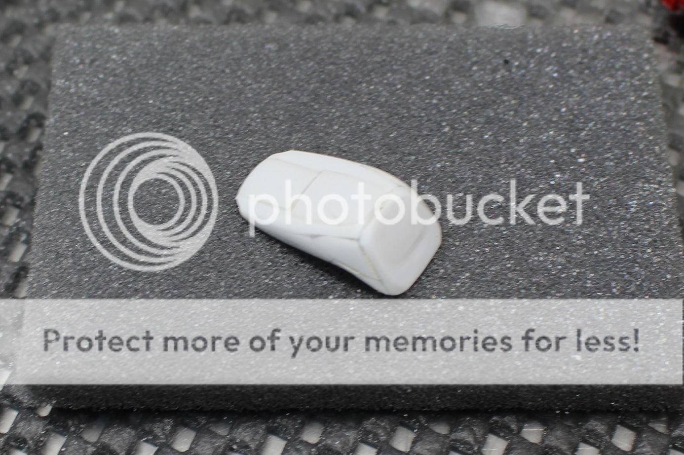
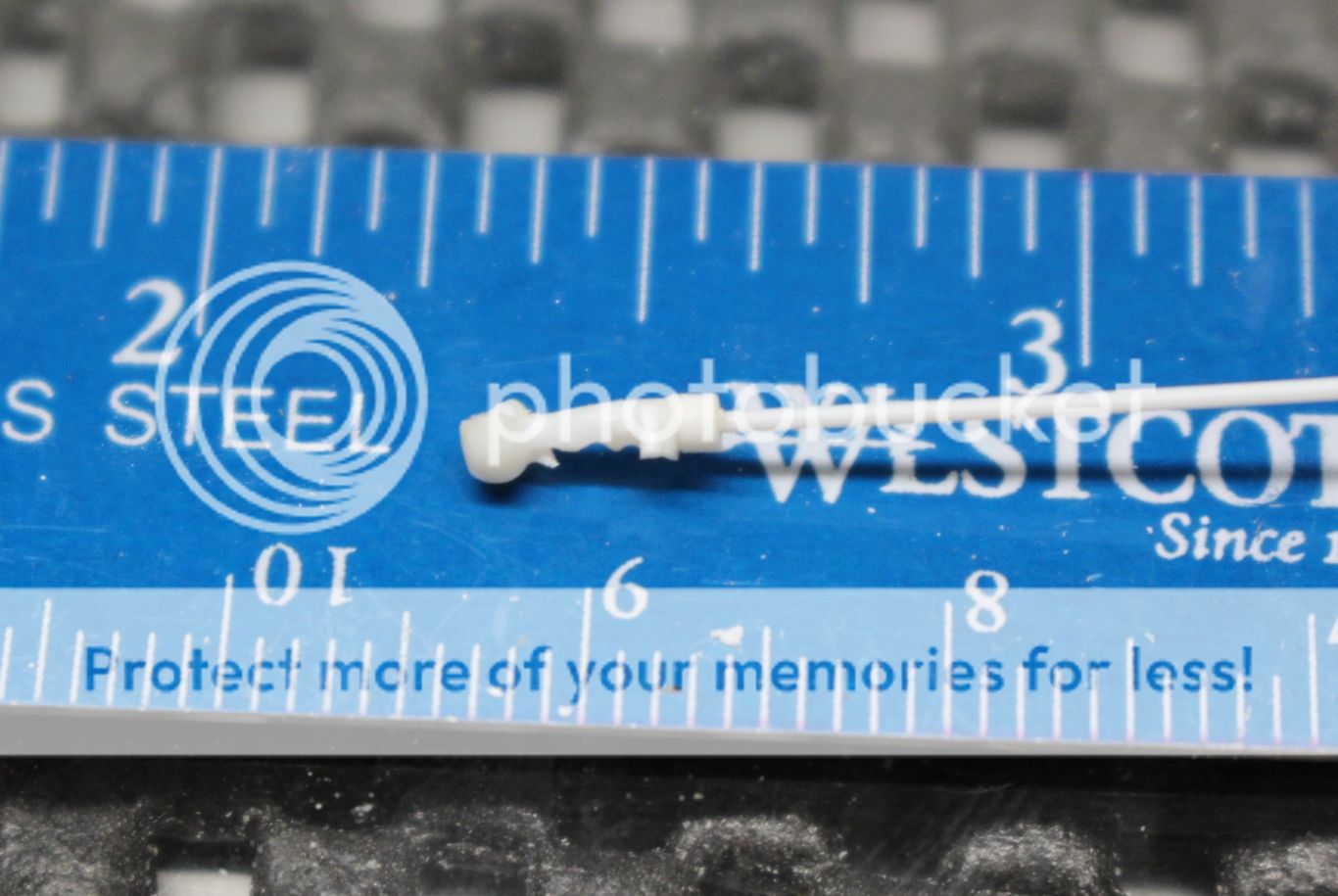
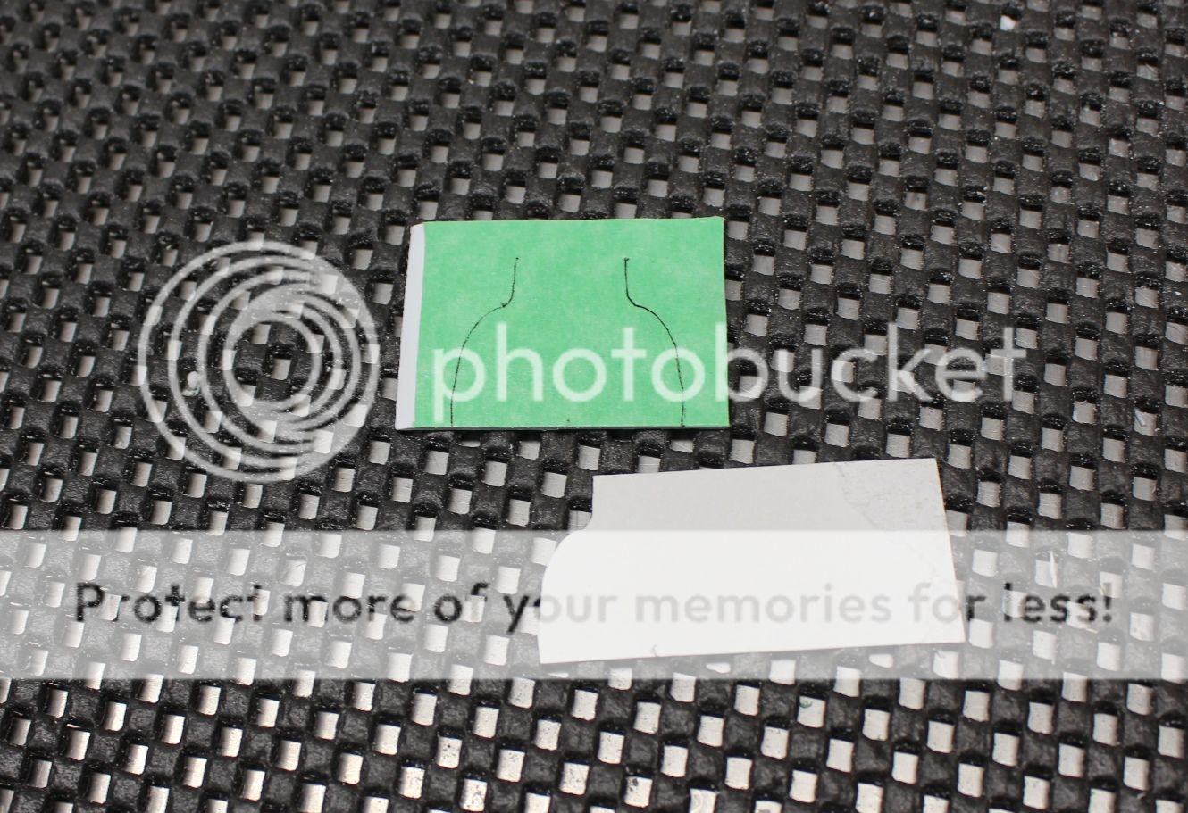
Next up was the seat. The seat in the Viper was a slightly modified bucket seat commonly available - RCi's high-back racing seat (p/n 8000S):

In the Viper they cut the head rest portion off that gave the seat more of a cropped look. Looking up the seat I had some basic measurements to work with, though there was a lot of eye-balling going on. What I want to end up with is about 15 mm wide, 21.5 mm tall and seat bottom of about 13.5 mm. I started by cutting various shapes of 1.0 mm plasticard and gluing them together to get a rough seat shape:
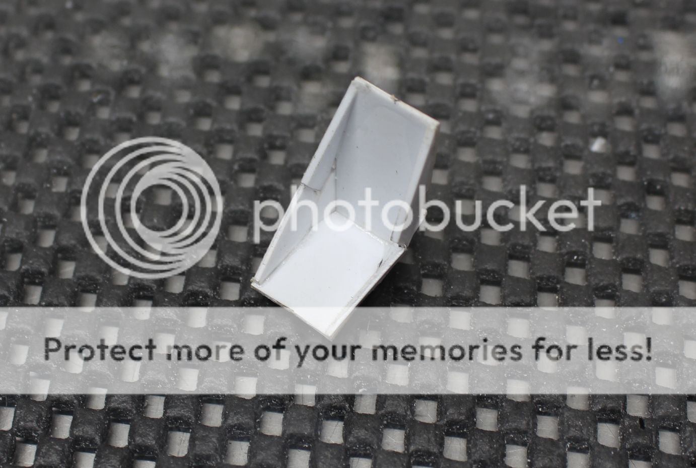
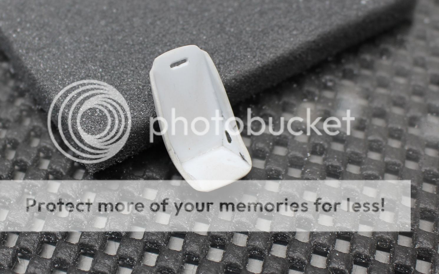
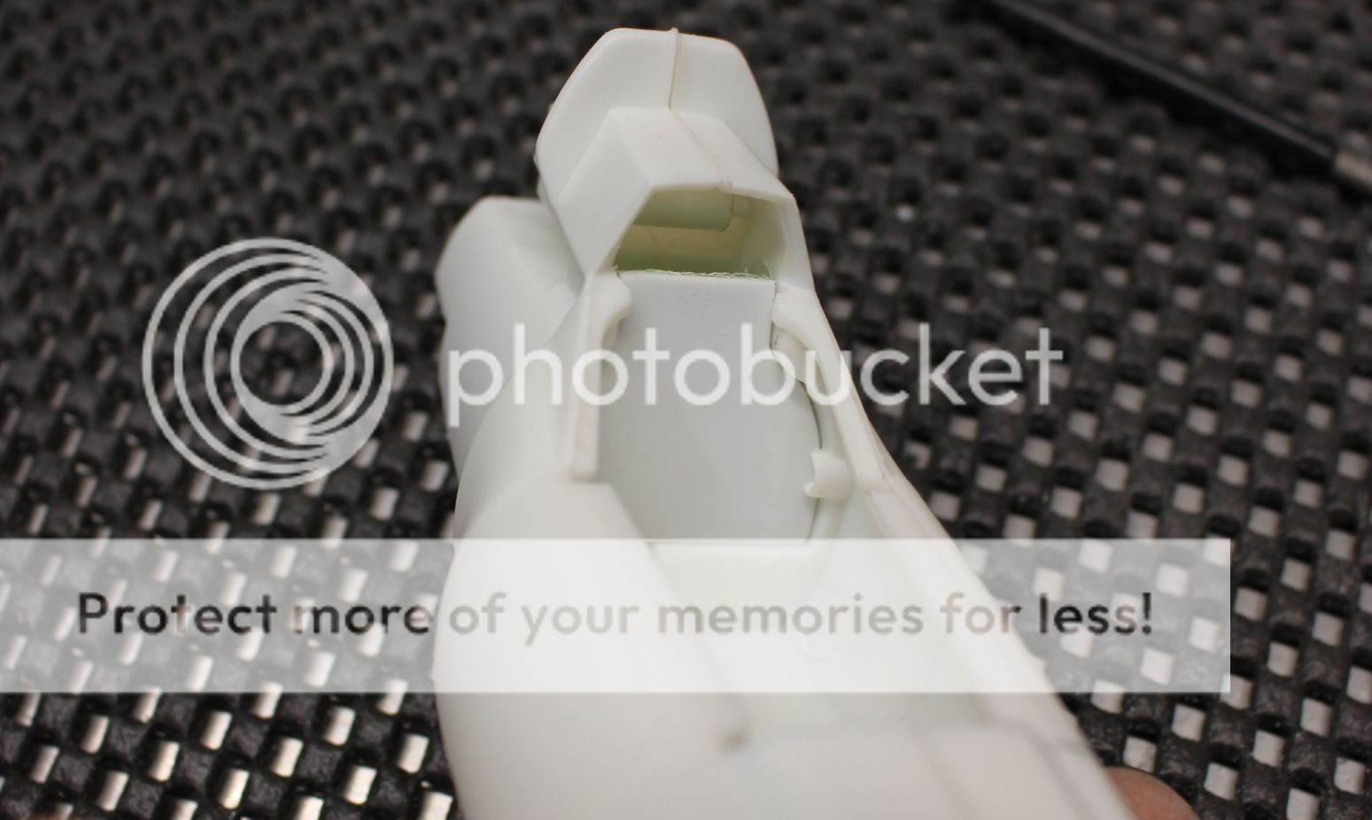
From there it was getting a rough shape by first using files:
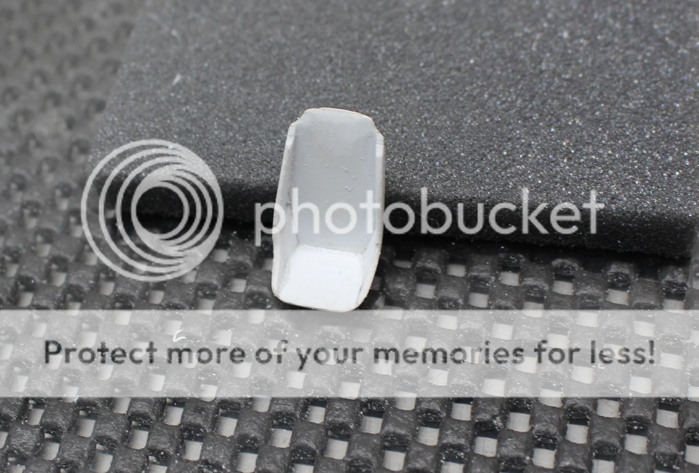
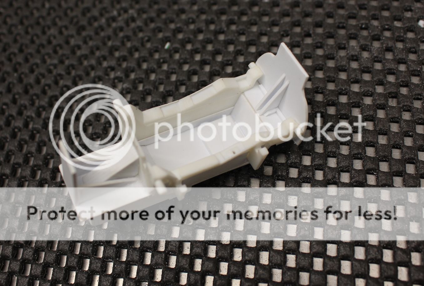
Once the basic shape was there I sanded the rest of the shape into the seat using 200, 400 and 600 grit:
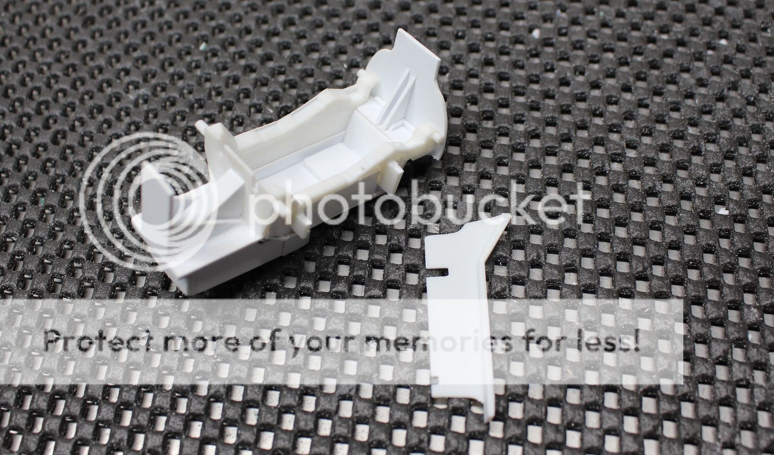
Then it was time to drill in the holes for the harness system. Oddly enough, even though the seat had a slot for the shoulder harnesses, the show didn't use it. The shoulder harnesses were fixed to the rear cockpit area behind the seat back. But more on that in future updates:
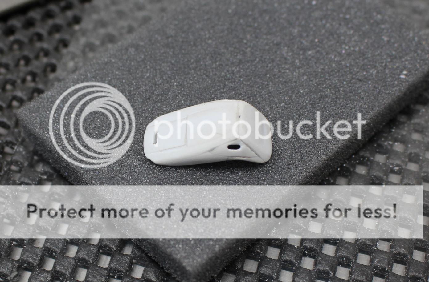
The seat shape was more of a focus on the outside of the seat and the inside was intentionally left pretty simple because the last thing that needs to be done is the work to represent the seat cover used. A quick covering of Tamiya white putty was applied and the seat cover will be made from it once it cures:
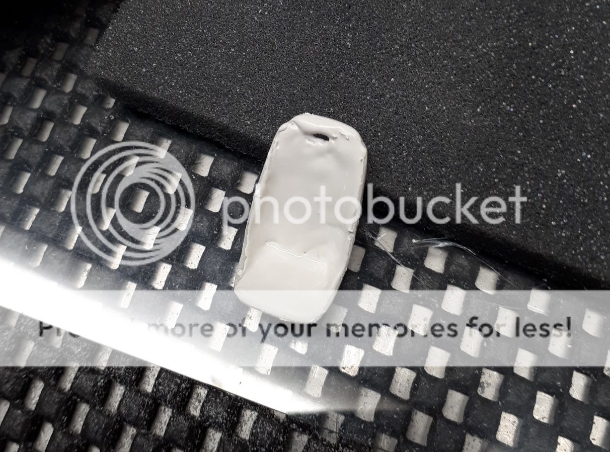
Once the putty is cured I'll be able to go at the cover and finish the seat off.
Thanks for looking!
Mark. -
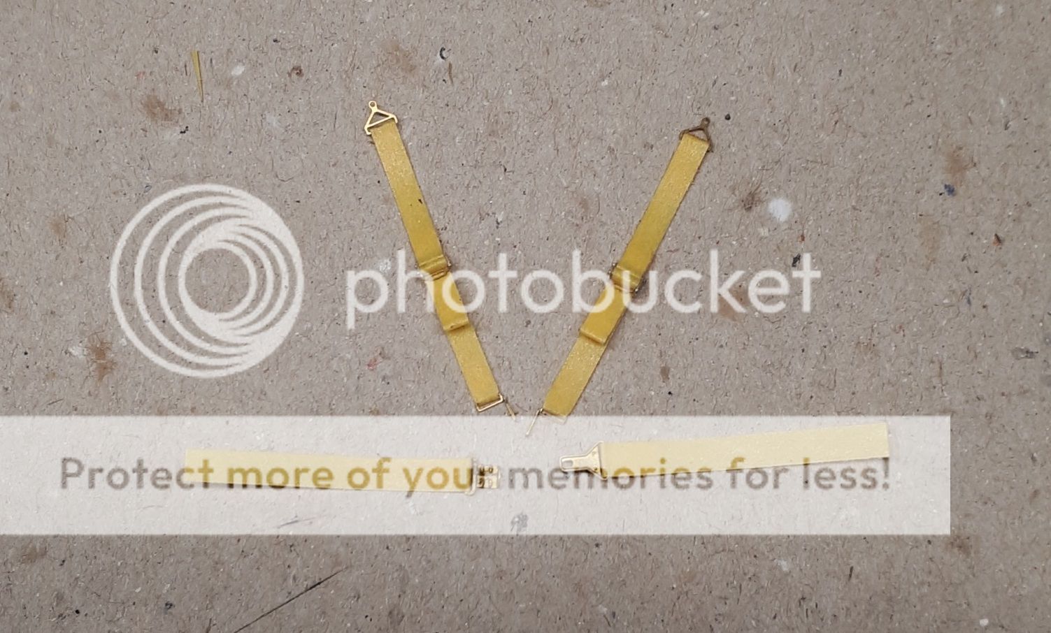
First up was the harness. The Viper Mk II had an RCi Latch Type 5-Point Harness (p/n 9210D). Although you'd think with the G's pulled in the Viper. Looking up this harness as a reference I started by cutting the scale 3" straps out of Tamiya tape doubled over. But soon it became apparent that Green Strawberry didn't do the same...
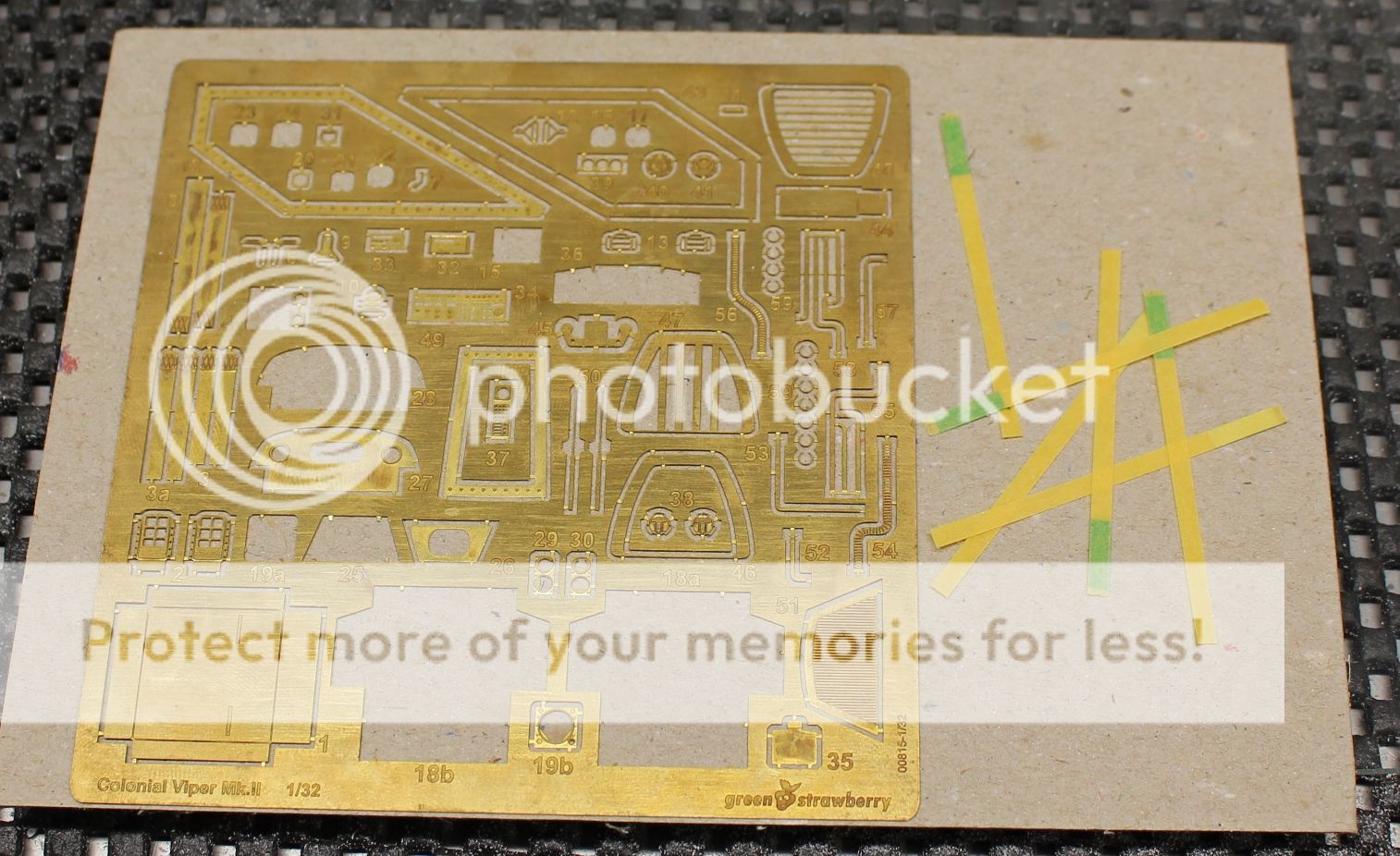
For starters, there were buckles missing in that the adjustments for strap length were present on the actual harnesses for the 4 main belts. The lap belts in the PE set were a good 3 inches, but the shoulder harnesses were not... minor thing, seriously. I'm not losing sleep over 1 inch (which in scale, really, 1/32 of an inch if my math is right). So I did a quick trim of the straps for the shoulders:
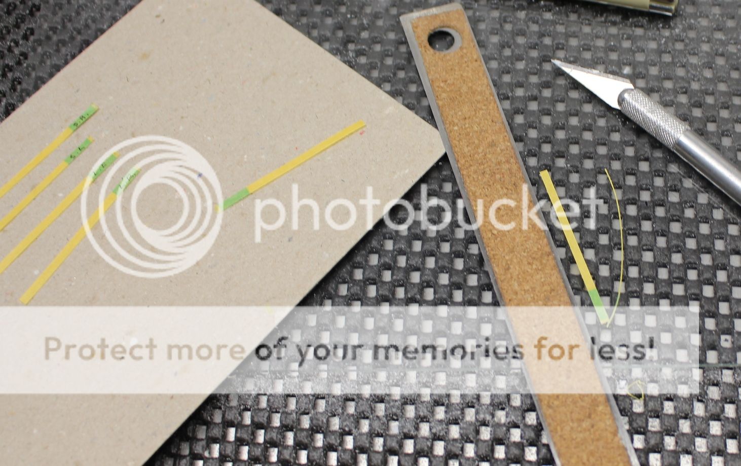
Even though it is a 5-point harness I noticed that there were no parts included for the fifth belt (the small crotch-strap, or "submarine belt" as the manufacturer calls it...) I went through a few reference shots and even though the seat had a cut out for the 5th belt, and they did fly in some wicked high-G maneuvers, the 5th belt was never included in the actual Viper. Alright! One less strap to make... but I didn't realize this until after the 5th strap was cut and ready. Oh well.
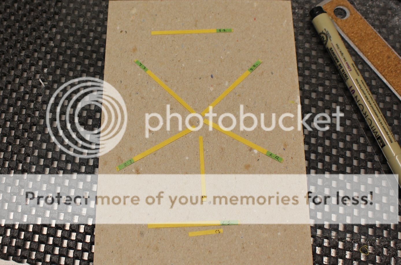
Now it was time for the assembly itself. I started with the shoulder harnesses and added two thin rods to the adjustment buckle to give the straps a bit of depth and for the construction to make sense. The corners of the strap that doubles over at the lower buckle was also trimmed to add the angle in the strap seen on the real thing:
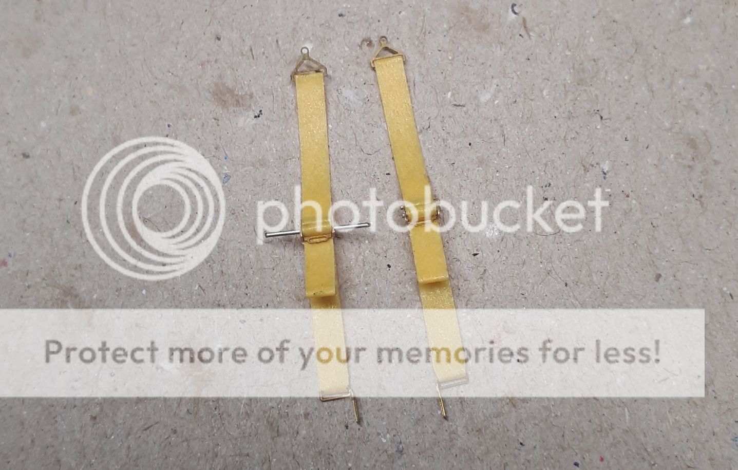
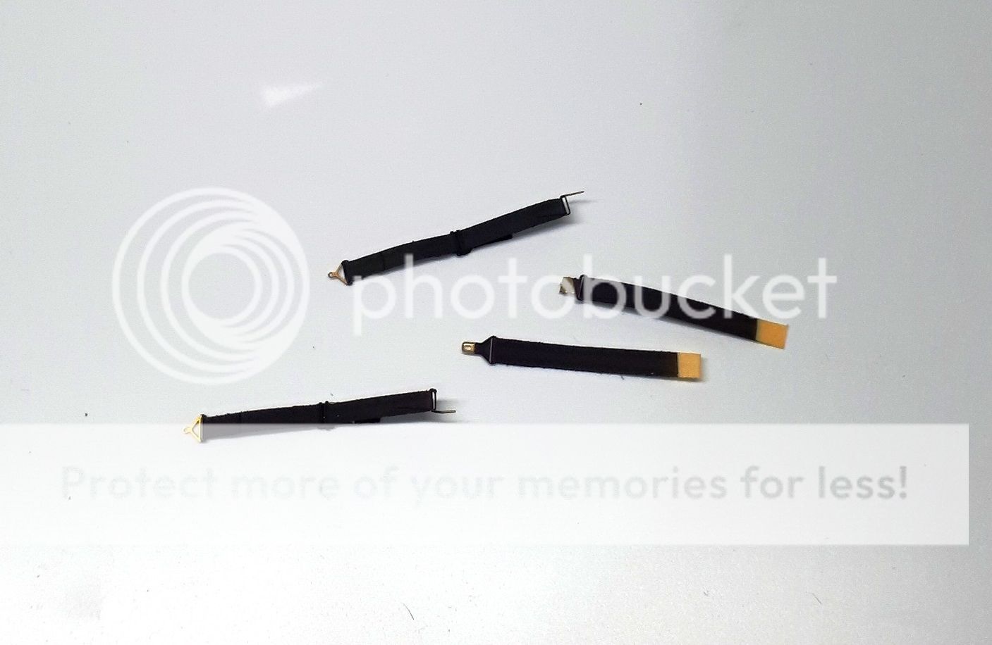
The assembly continued with the lap belts which were made much easier by the lack of the adjustment buckles:
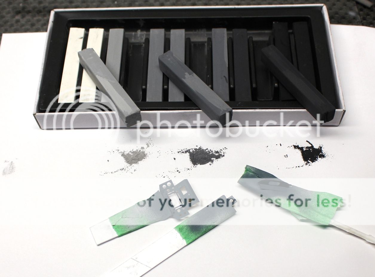
Next up the straps were all airbrushed a thin layer of flat black enamel rather than acrylic so that the paint adheres to the tape as it will be bent around (where the acrylic tends to flake off):
Once dried I took a cut down (read: pointier) toothpick and applied the silver to all the appropriate pieces. I also fabricated the small leather patch to add below the one waist belt buckle:
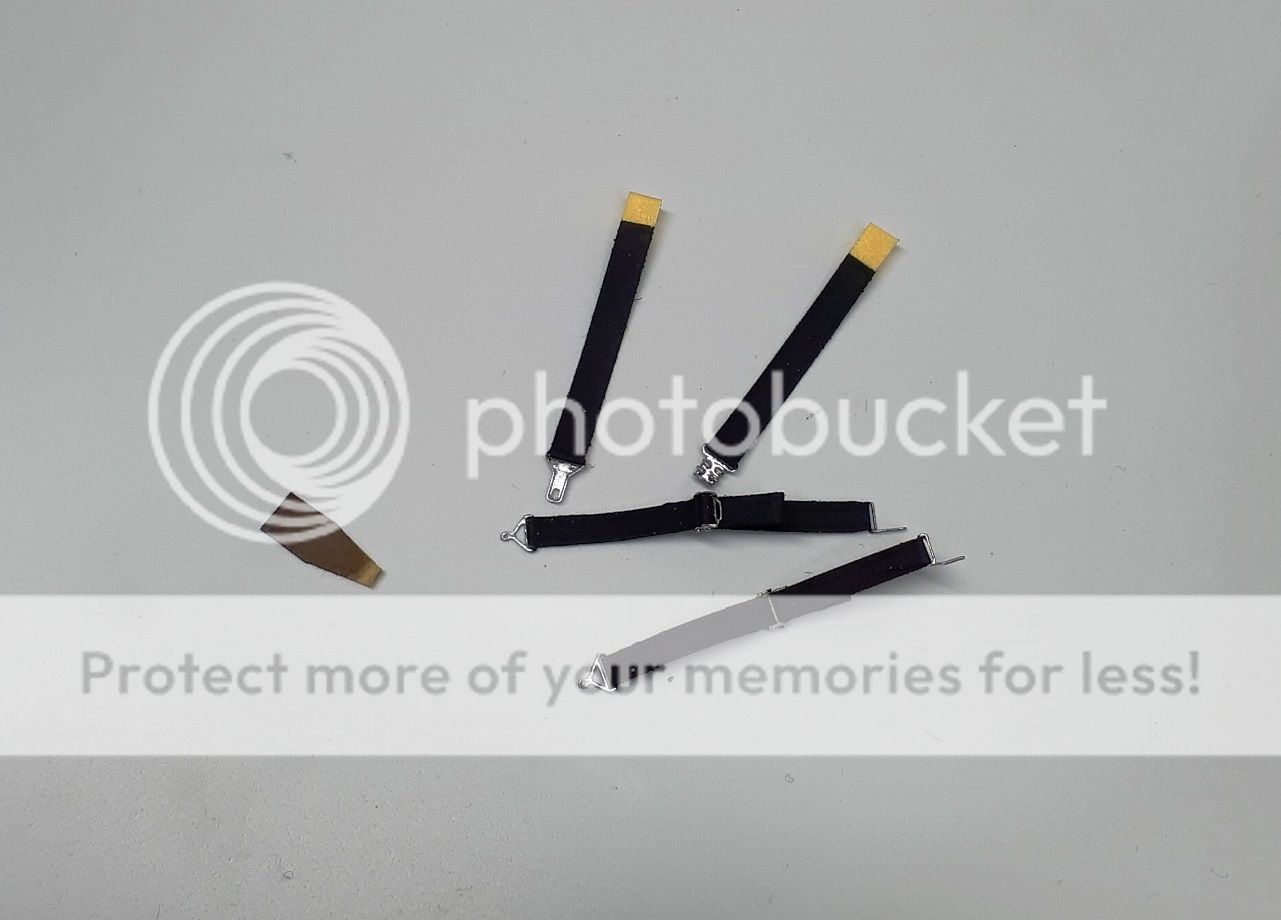
Lastly the straps were coated with some dark grey pastel chalk in some places to add a bit of depth to the colours of these straps, the leather piece was attached as was the hook on the other waist belt buckle:

The matter of the missing waist belt adjustment straps isn't really any issue at all. The plan is to have the Viper sitting and prepped for launch or a scramble. As such, no restraint system would be either done up neatly or on the seat itself. The two waist straps will be fed up through the openings in the bucket seat and then hanging onto the floor so you won't see the adjustment piece even if it was there. The two shoulder harnesses will be flipped up and over the side walls so that the pilot can quickly grab them and do up the harness once they're in the seat (oh Starbuck, the things I do for you...)
Now with the harness complete, it's time to build the seat and rear cockpit that these will attack to.
Cheers! -
Impressive build Brett! Very clean and crisp paint work and the lights add such a nice touch. Definitely setting the bar high on this one!
-
Nice work Brett! Very crisp and clean work!!
-
On 8/23/2019 at 11:38 AM, The Madhatter said:
fantastic job on that console Mark. You should stick an LED behind it

 Hahahaha
On 8/23/2019 at 9:36 PM, Ikon said:
Hahahaha
On 8/23/2019 at 9:36 PM, Ikon said:That panel is a thing of beauty! Such a great job, esp with the horizon.
Thanks Ikon. Really glad it all worked out.
9 hours ago, Brett M said:Beautiful work on the console. I can imagine that the entire cockpit is going to be stunning when you’re through with it.
Thanks Brett.
Work has continued on the seat with the cockpit. There are three things simultaneously going on; the seat, the seat back, and the harness. But rather than a full on back-and-forth between the three, I'll post them up as an update for one part each. Right now the putty is drying on the seat and seat back as well, and the first coat is drying on the harness. Looking like the updates won't be up for a bit still. Regardless, thank you all for following along this build. The light is at the end of the tunnel for the cockpit.
Cheers!
Mark. -
I started with the smaller LCD screen. I shot it with dull-coat and then back painted white for the four small buttons on the bottom left of the LCD panel:
Next up were the gauge faces for the outside panels. Be forewarned, you need to trim about 1.0 mm around the edges of the black printed ink on the acetate for the two side panel gauges (H & G) for them to fit both on the panel edges and the inside bend. The overlap can be trimmed afterwards, but it is a lot easier to just cut them right away on the film... ask me how I know... anyway, here are the side panel gauges:
The exact same problem with trimming the center film piece (A). It's not bad on the bottom, but the top and sides also need 1.0 mm trimmed off to fit right. Anyway, fool me once, right? Test fit before glueing for frakkin' sake... the panel went in, and although the gauges lined up, the buttons really didn't. Further to that, I was really disappointed with the acetate buttons along the sides and bottom of the main screen:
They're flush buttons with the panel. This could have very easily been etched into the PE panel itself, and then allowed the builder to cut the acetate film piece so the 3 gauges on either side could be glued on their own like the side panel pieces (G & H). Not liking the buttons, I used a strip of 0.28 mm x 0.56 mm, painted the one flat face black, and then used the edge of my knife to scribe the squares for the buttons:
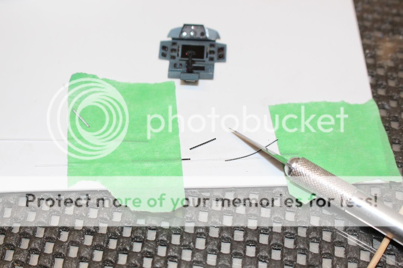
As you can see it took a few practice pieces. Medium glue was applied to the opening and using a toothpick the strip was pressed into place: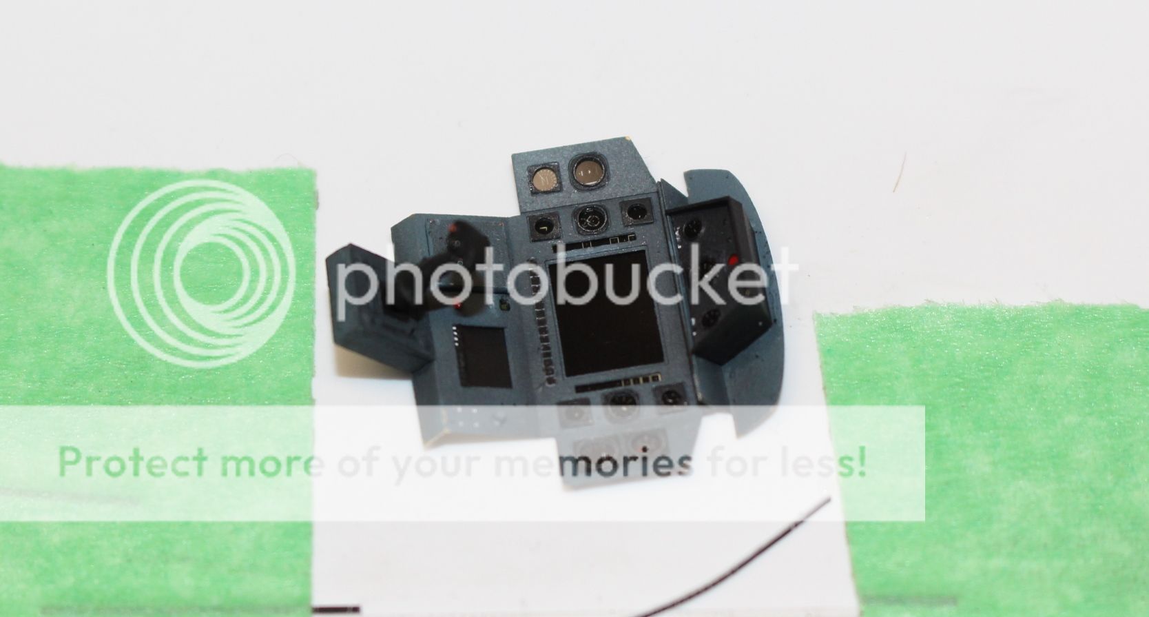
The same process was then applied to the side buttons. Once they were in, wanting to make it look like a well used (but maintained panel) small areas that had chips from assembly were touched up with a fresh application of Intermediate blue:
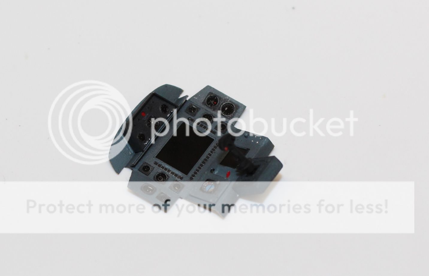
And there we go! Panel is done:
I am honestly impressed with the Green Strawberry panel. Sitting here looking at it, it definitely it gives me the look I want - a used instrument panel with the aircraft power shut off. The modifications to the buttons and the artificial horizon would have been made much easier if the buttons were etched onto the panel, and the acetate film allowed you to paint the ball the way it was, but that's going a bit further than is honestly needed to get a good Viper cockpit. There are a few things that I wish this panel and set came with such as stencils or decals for the writing on the panel. It's in 1/32 scale and there is more than enough room to add them.
But those are small little things. Let's be completely honest here, short of diving into a scrap bin and finding decals for the gauges there would be no way I could make the instruments themselves look the part, and for that I'm thankful for this set. It's a HUGE improvement over the softly molded kit panel and well worth the $20 I paid. And that's just the panel parts used so far! This set still has a lot more that will still be used and the inclusion of both early and late panels is fantastic, giving the builder that much more of a choice on the particular Viper they want to build.
The next step will be the seat construction, and once that's done, it'll be the rest of the cockpit and nose gear. For now, the panel is being put somewhere safe as more work is still to be done.
As always, thanks for looking!
Cheers,
Mark. -
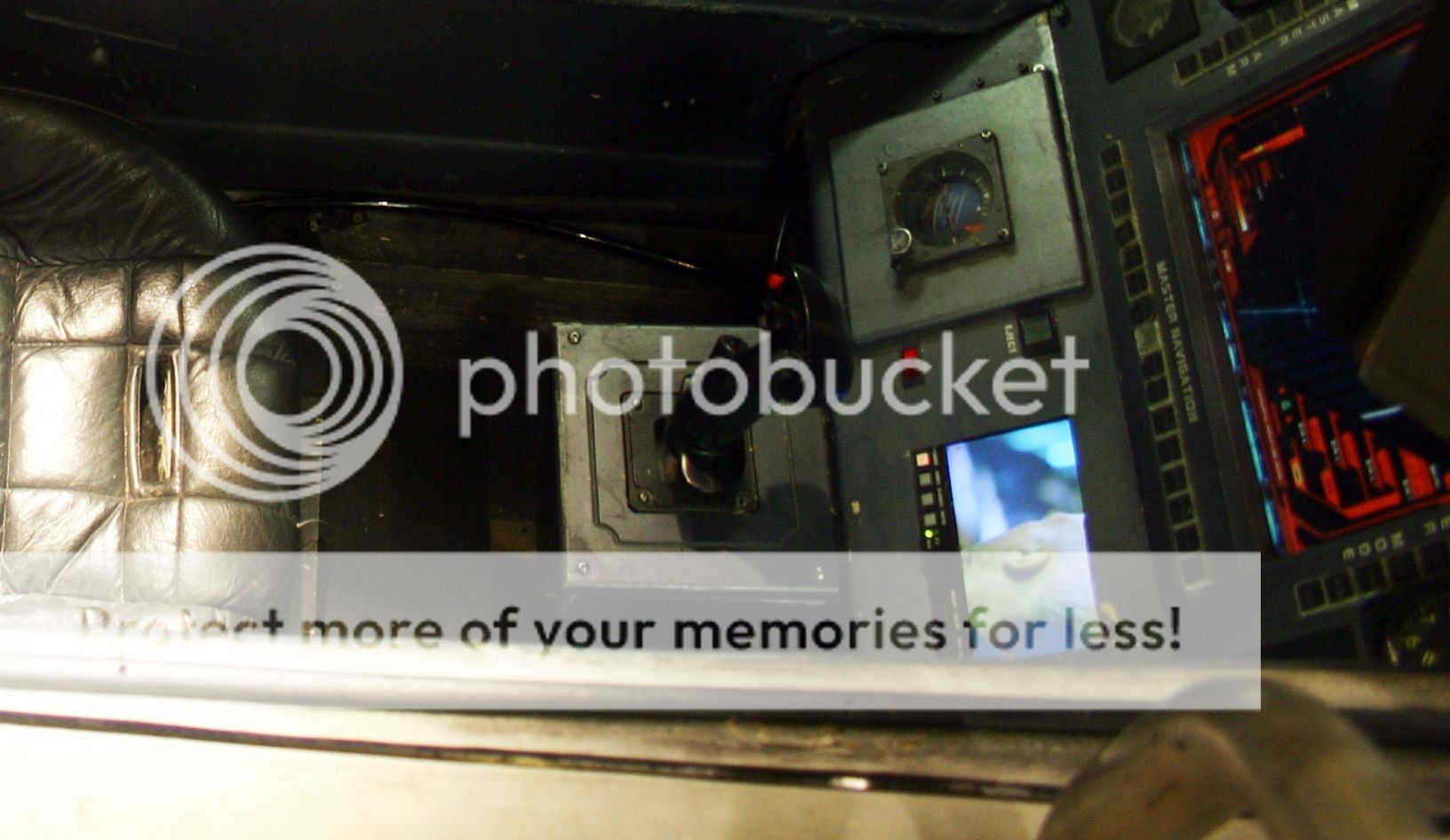
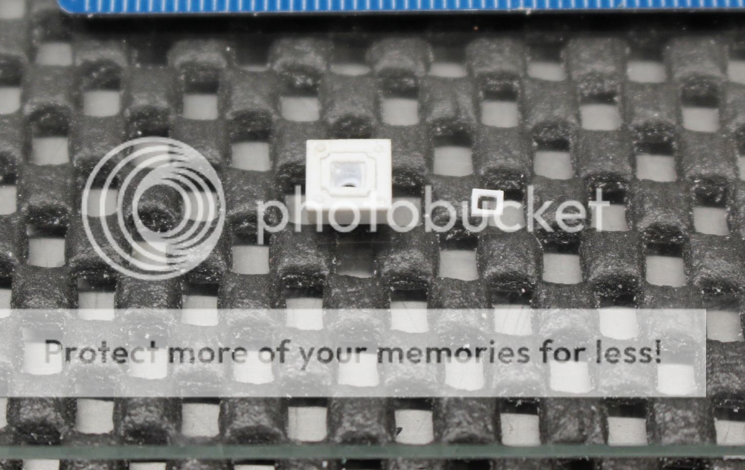
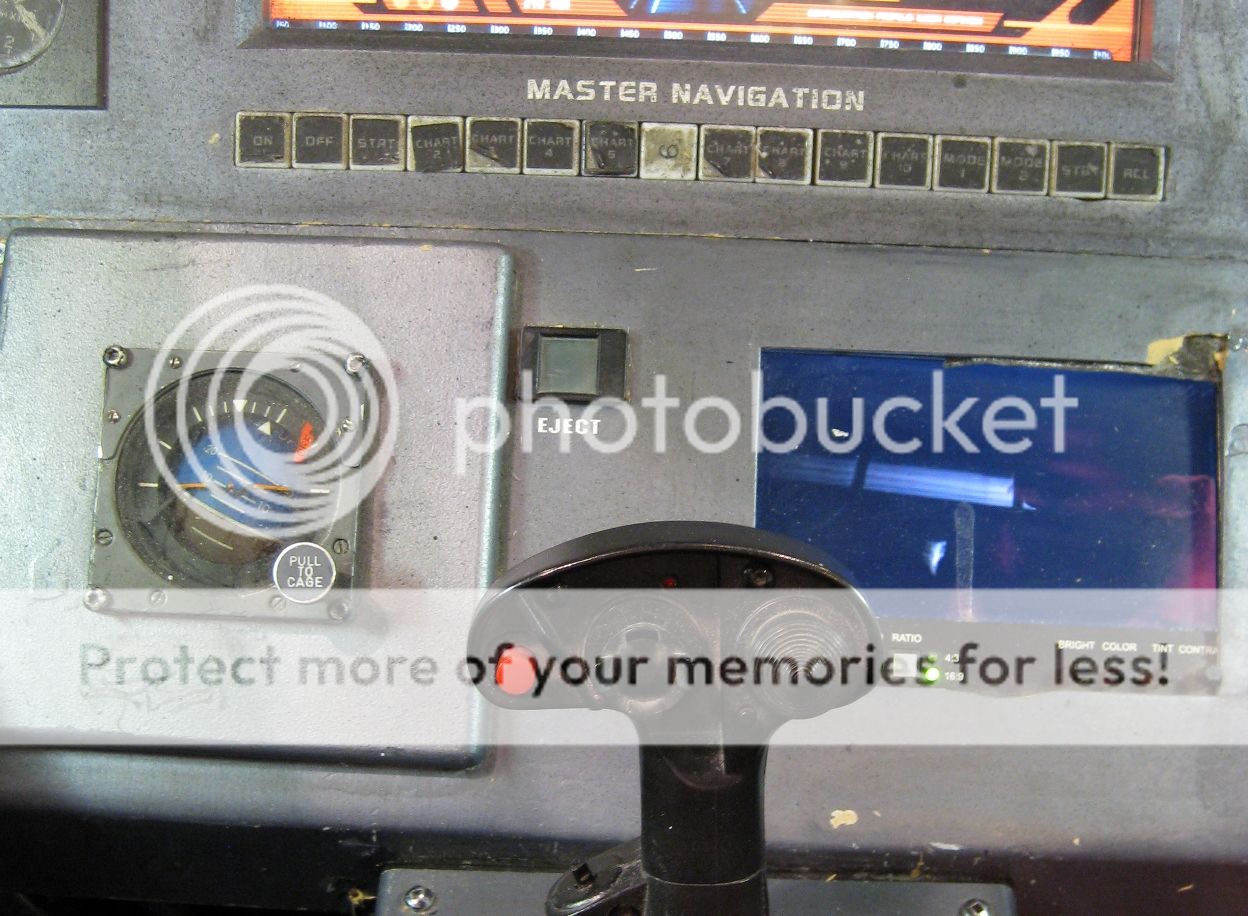
Brett they were very creative with parts used for the prop Vipers. Lots of great reference material out there, although the prime site I was using to build up a plan suddenly is down once I decided to start building this model. Go figure. I've emailed the webmaster but no answer as of yet. So, using some of the pictures from google search and this is a great reference for the artificial horizon (and buttons I'll talk about later on):
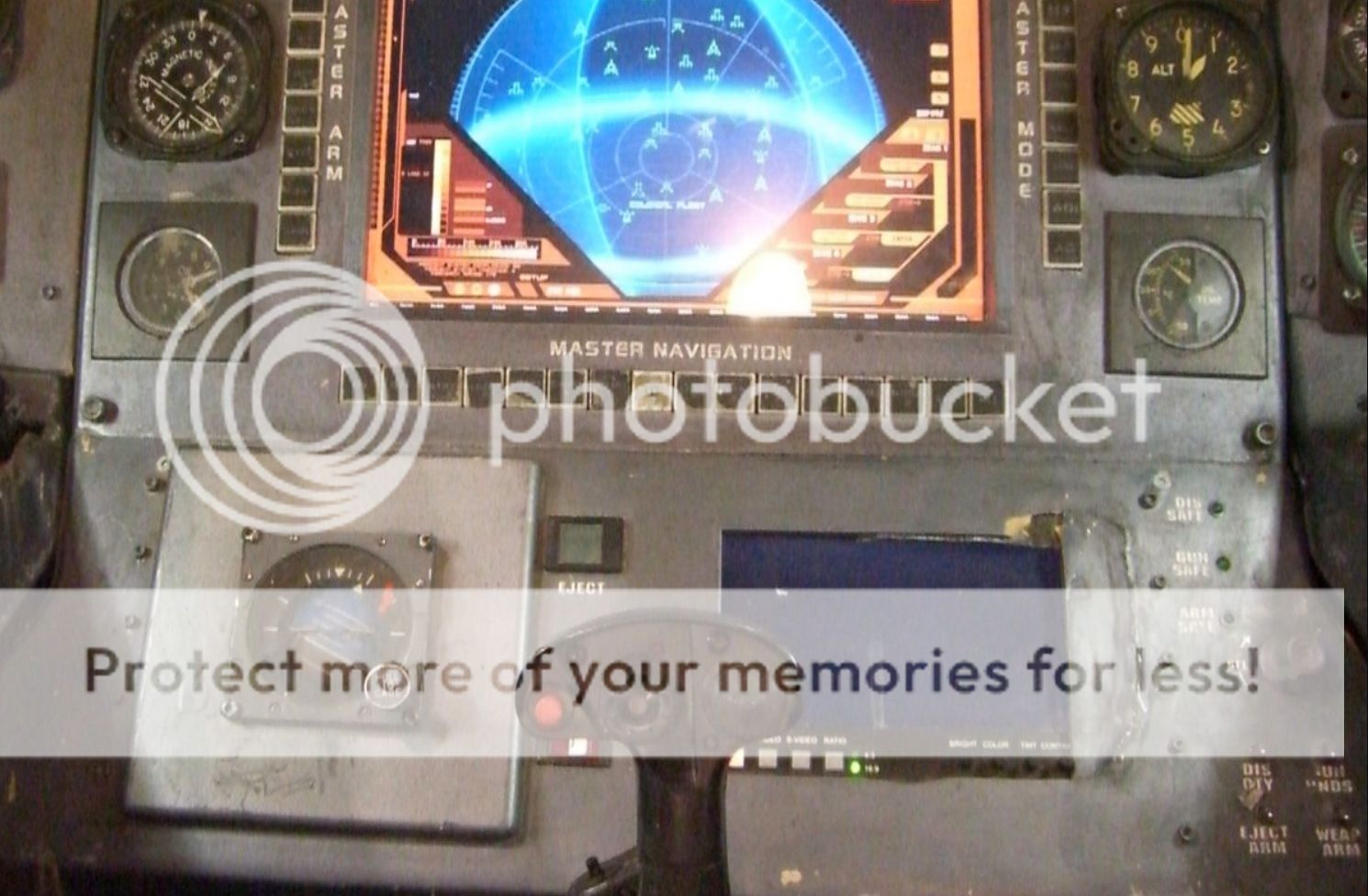
Things garnered from this image:
-The artificial horizon assembly (housing holding the gauge) is significantly raised on the main panel;
-the buttons are flush with the main panel;
-the small LCD screen is flat in it's finish, not a high gloss;
-the bottom 4 toggle switches are silver;
-there are three small green LEDs just above and left of the selection knob;
-the main LCD display has a glossy finish to it; and
-the altimeter has a yellowish finish to it (as was painted on the acetate plate).
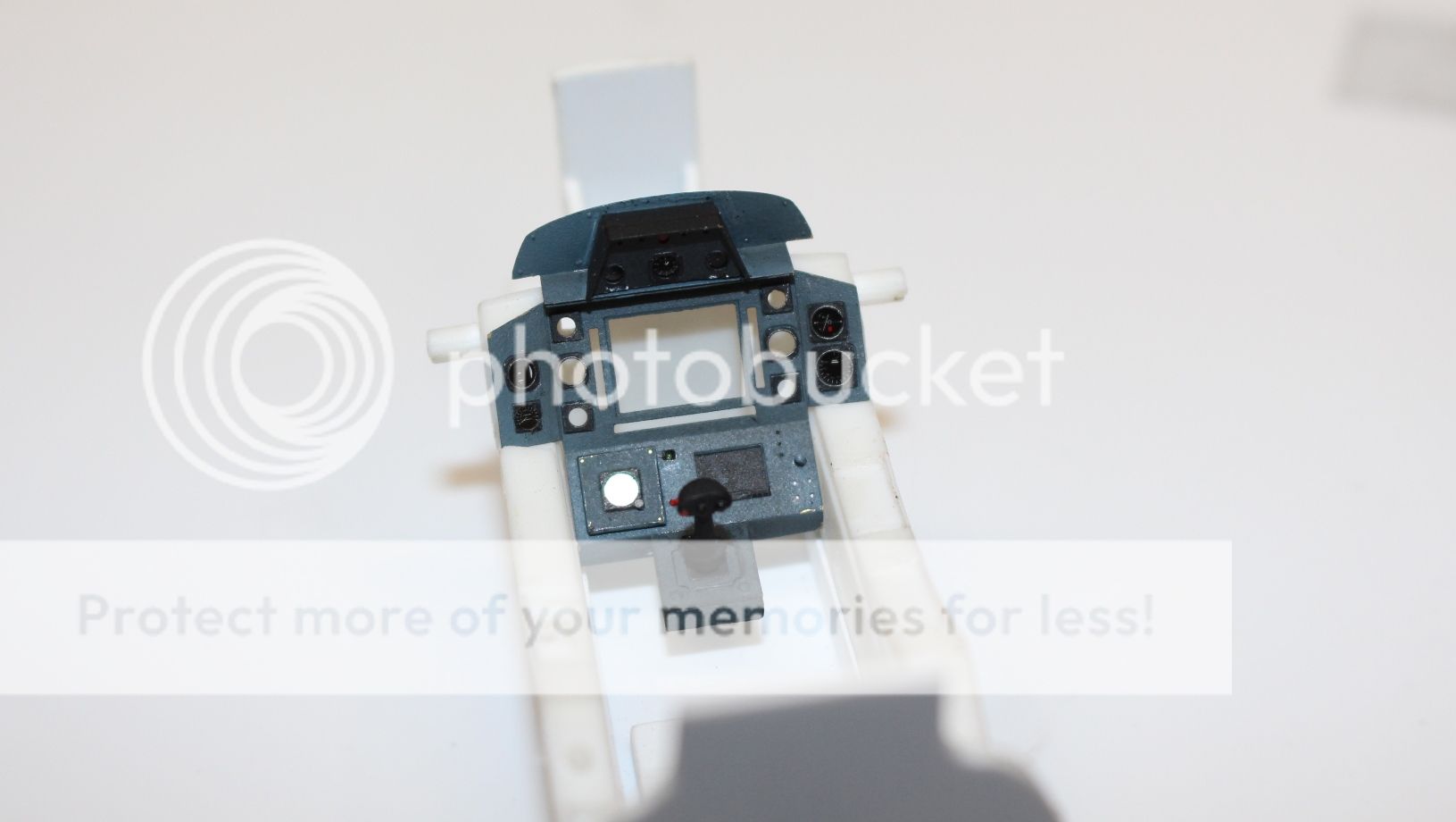
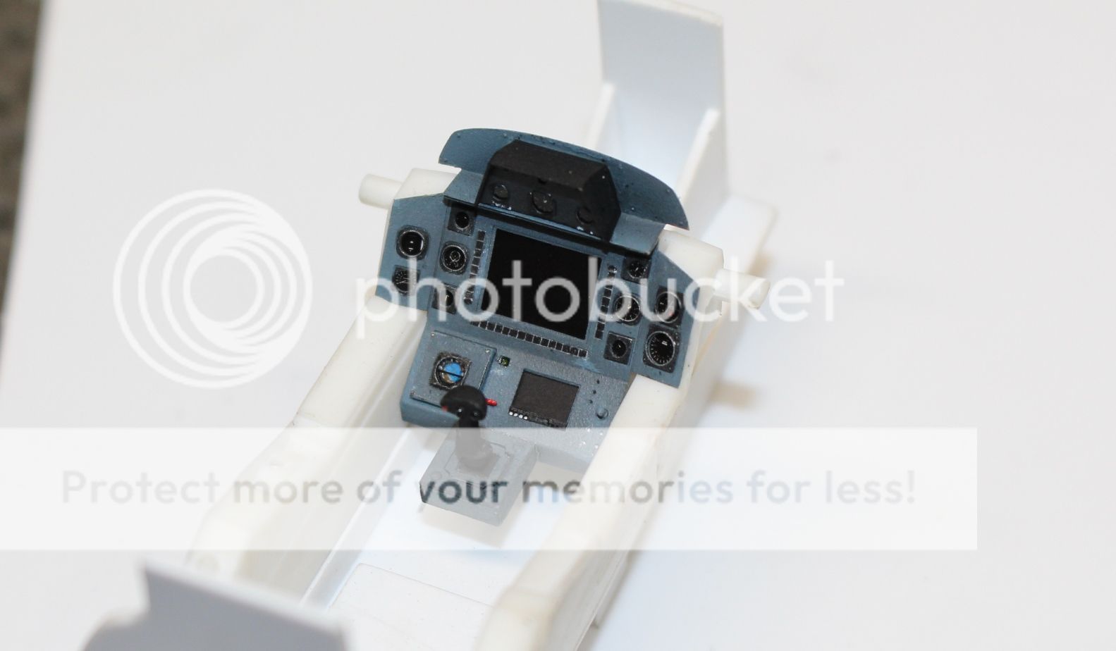
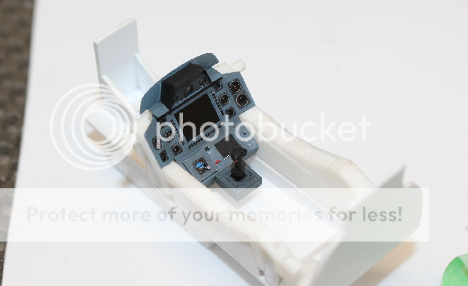
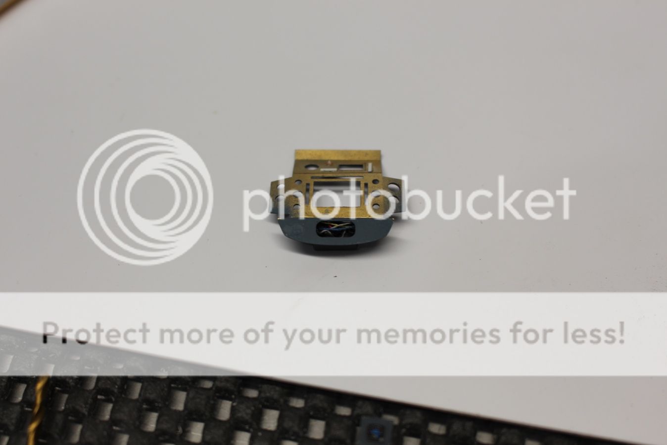
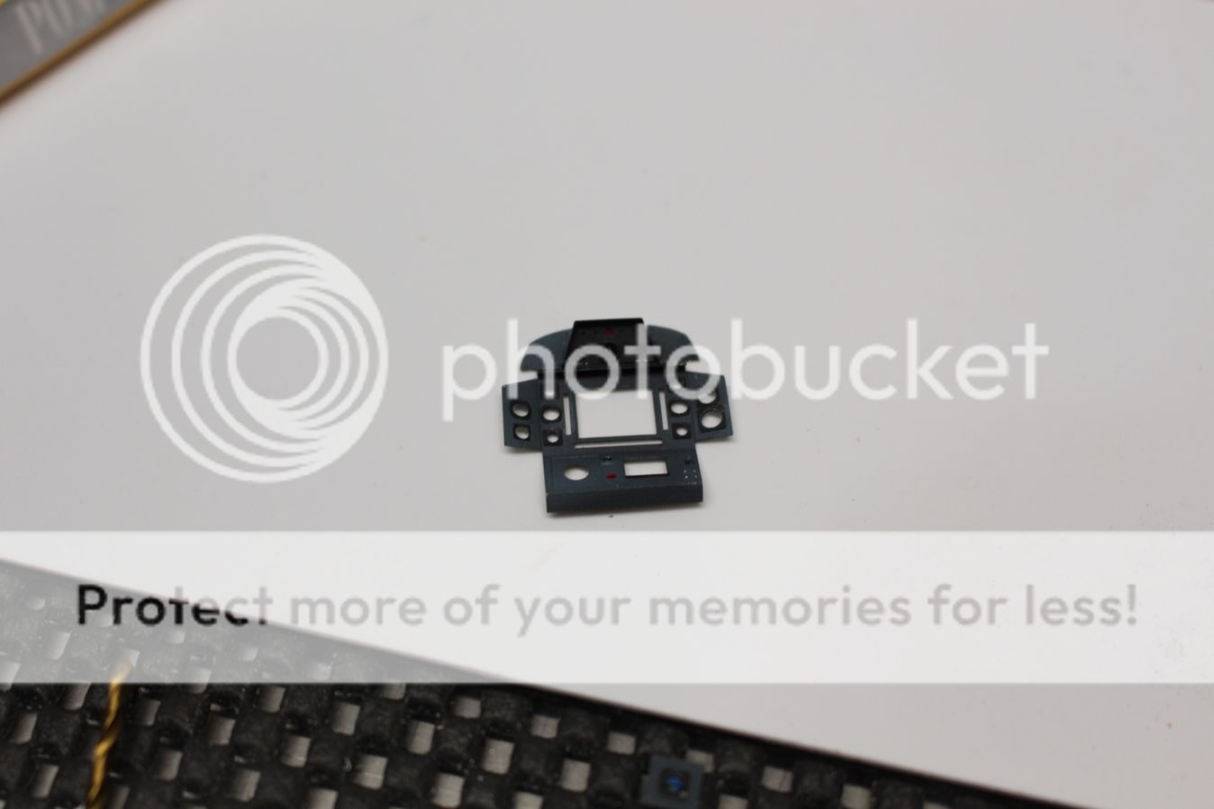
Work started with the HUD as this was the easiest piece to work with to start out. There is a cut-out that is visible when looking back at the HUD assembly when the fuselage is glued together, so I also added a few small 2.0 mm x 3 mm rods to simulate the actual gauges and then glued coloured threads as wires to give some depth in there. Once dried it was glued to the main panel. Details were then added to the main panel, including the red switch, green ejection button, and the silver switches, selector knob, and using medium superglue and green paint, the LEDs were added from behind the panel:

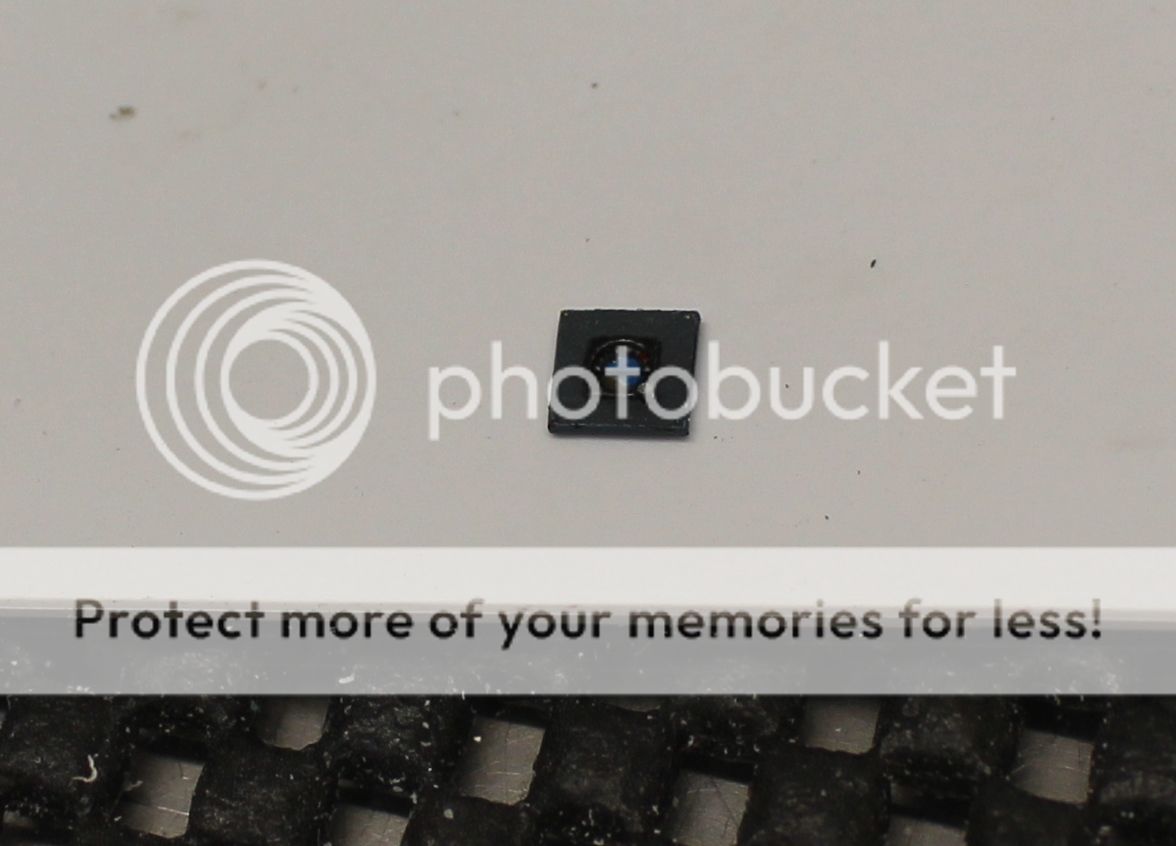
The kit piece for the artificial horizon is much like the gauge bezels with a small sunken area to put the PE piece for the gauge... and the acetate film is a simple black gauge (on the acetate plate pictured a few posts above, it's D). I started first by painting a portion of a pin head as close a blue and brown as I could match to the reference image (tamiya X-14 and testors brown mixed with a couple drops of black):

The next step was to try and get the black ring around the horizon ball. I drilled a 1.5 mm hole in some scrap 0.2 mm plasticard, painted it black, then using a cut down toothpick to add the white and red. It looks messy, because it is, but very little of this will be visible:

The pin head was then glued to the back of this piece matching the attitude in the reference image as closely as possible (read: someone forgot to cage the ball). The pin head was then cut down and sanded smooth with the black piece and then cut down to match the shape of the PE piece. The PE piece from the kit was given a scrap section of the acetate with the thin boarder line that was glued to the back:

The parts were then glued together and the edge was painted the Intermediate Blue of the panel pieces:
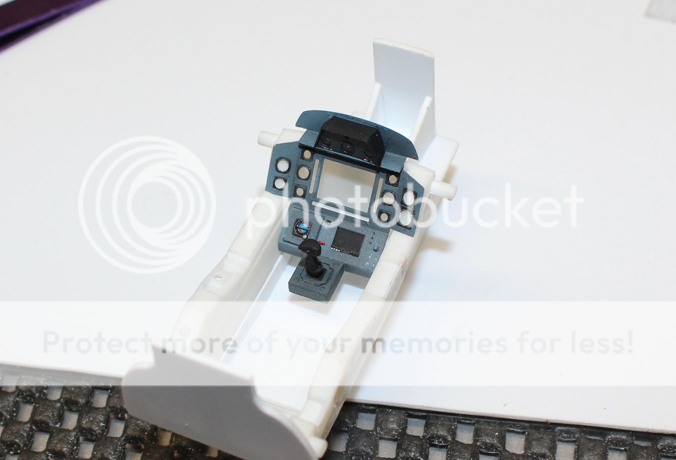
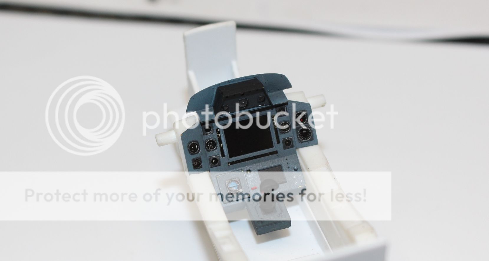
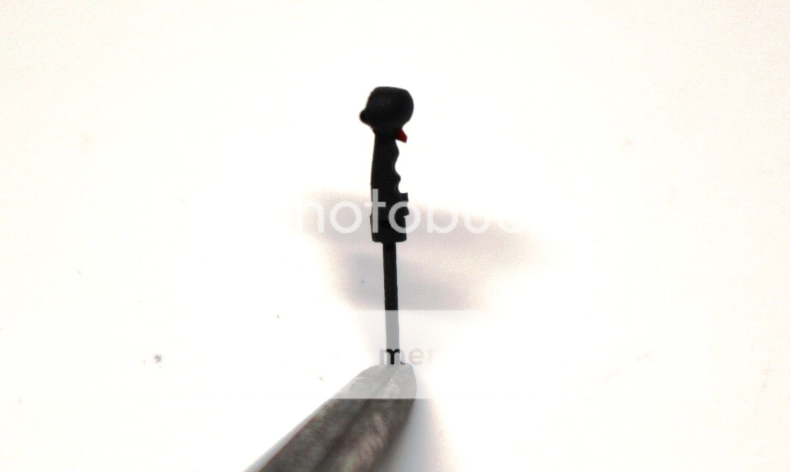
Once cured it and the joystick were ready to glue onto the panel:
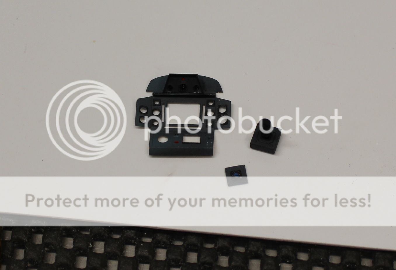
And here they are finally in place:
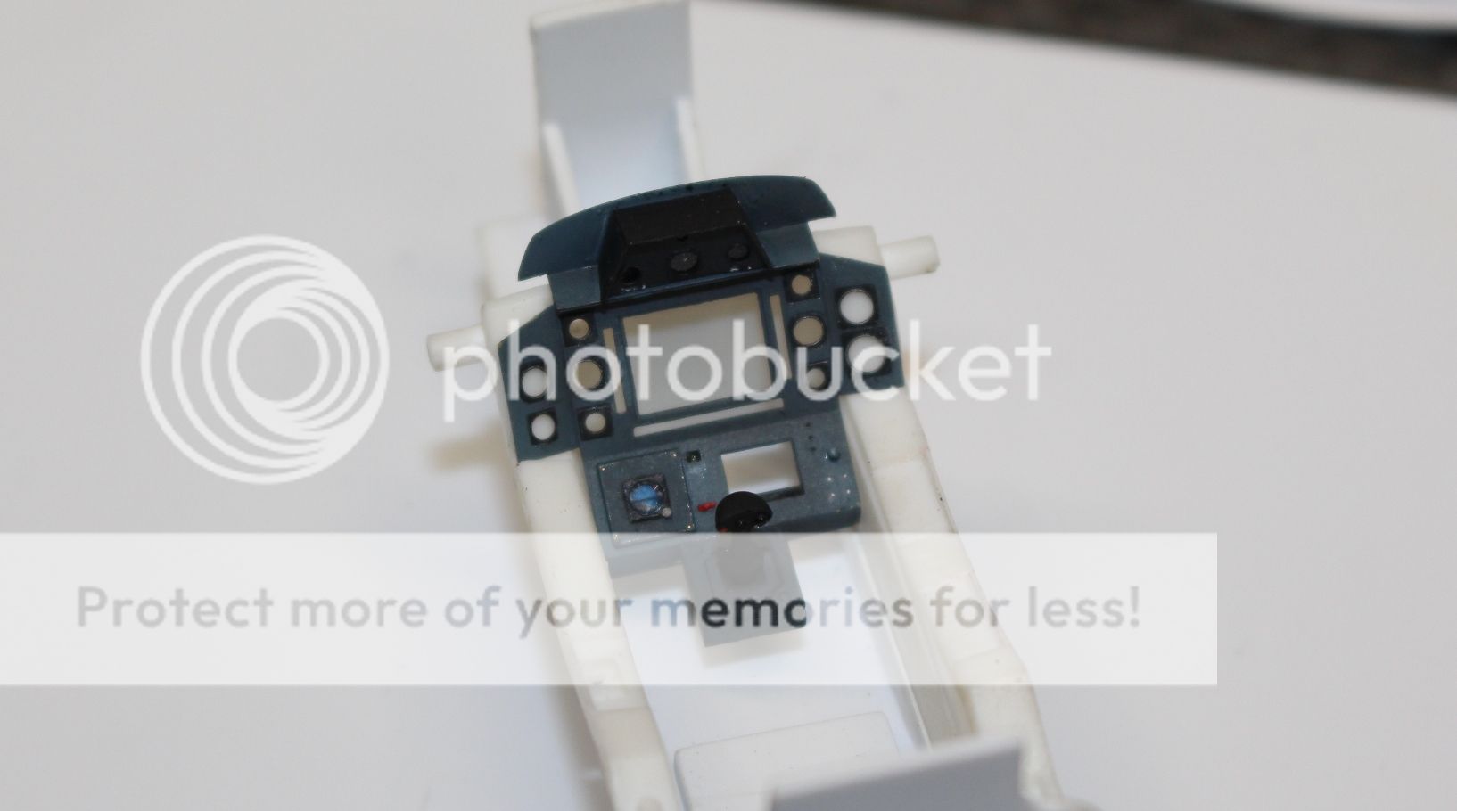
I am very happy with how the gauge turned out and how it sits higher up now than the original PE piece setup would have been. In the next update you'll also see why I'm so happy... there is some noticeable depth in the gauge with the black collar and the round artificial horizon. And with that, onto the next steps; final assembly and gauges for the panel.
Cheers!
-
I swear if you were to just add a black, star filled background and have just the K'tinga there it would be right out of the movies! Amazing work good Sir!
-
22 hours ago, Ikon said:
Outstanding work on that cockpit.
Thank you kindly Ikon. Greatly appreciate the comment.22 hours ago, Brett M said:I'll echo icon. Definitely looking the part of a Viper now.
Now.....where are those pictures of the screens installed? :)
It's becoming a Viper alright Brett! Slowly.... slowly.... so the screens aren't installed yet as I'm still building up a few other parts and pieces around and adding details to the panel. As I use both medium and fast CA glue I want to wait on installing the acetate film to prevent any fogging/frosting of the gauge faces.
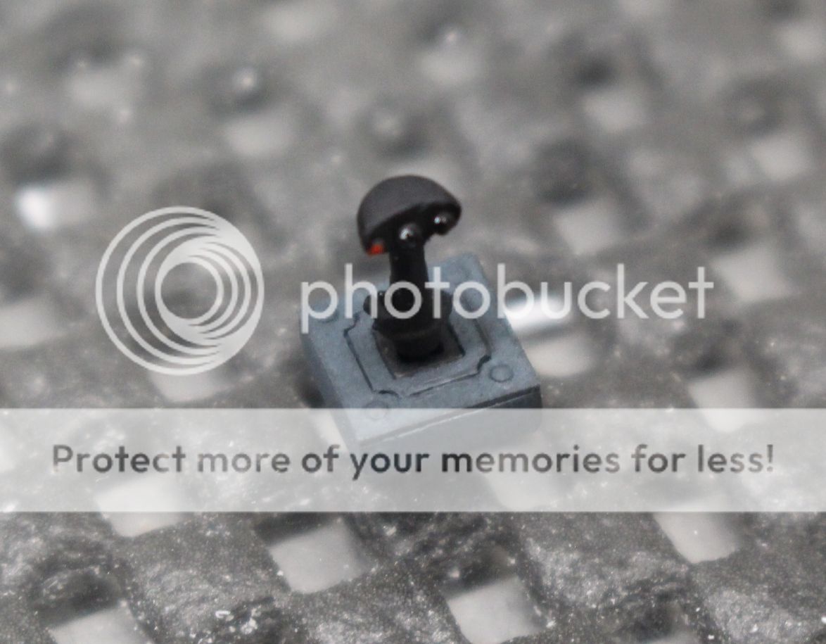
That being said, work on the control stick.... seriously, a joy stick, was started.
The stick in the cockpit:
The box around it is built up around the joystick, but the stick itself is nothing more than the SFS Flight Controller made by Suncom (the old joystick based on the F-15 control stick). Not having a spare F-15 stick in 1/32, it came down to cleaning up the one that comes with the kit. So I started by making a small box out of plasticard and the kit stick itself:
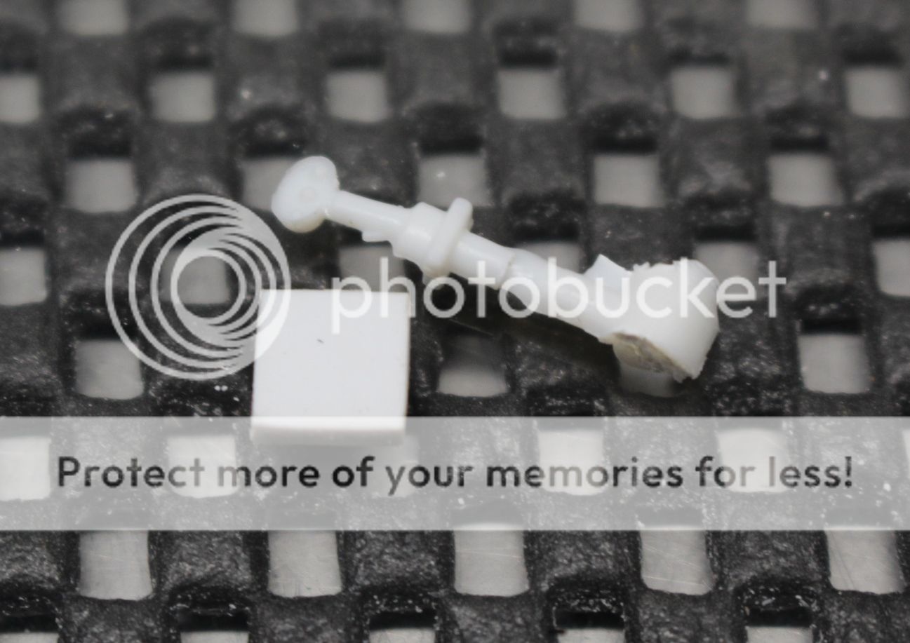
I started with the box. Wanting to have those panel lines emphasized by pastel chalks I decided to start out by using some 0.2 mm plasticard and cutting the sections individually. I also removed a small portion from the box center in order to give it a bit more interesting depth as well. Here are the 4 pieces (with the outer piece given some screws for the 4 corners:
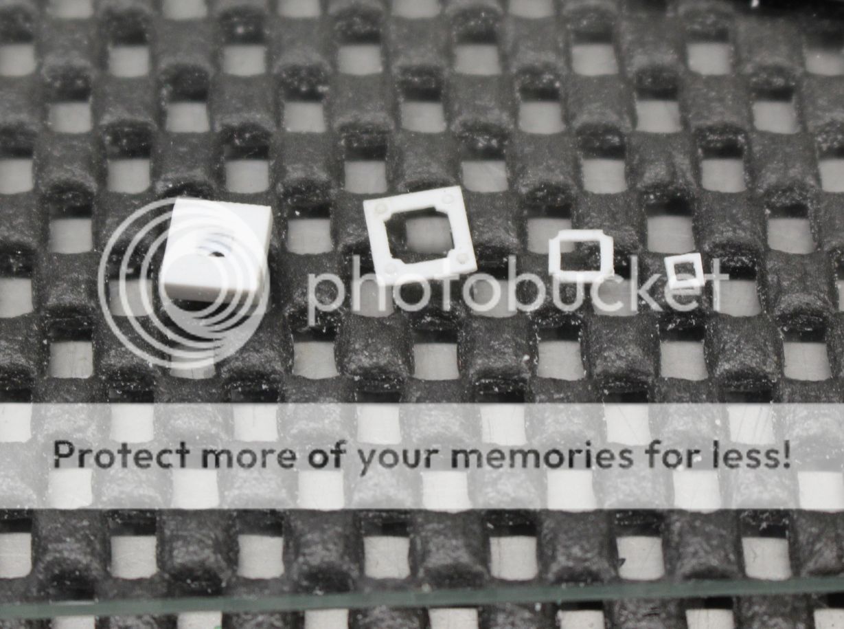
The first few pieces were assembled and ready to be painted:
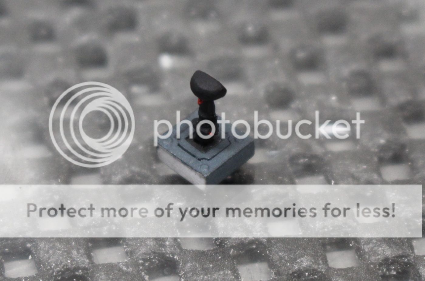
The box and face pieces were painted in the same colour as the panel and given a pastel chalk wash. The small center piece and the opening in the box were painted flat black, and then put aside to dry. My focus then went to giving the stick some shape, a trigger button and a pinky button:
The stick was then painted black and the buttons painted either a bright red or a gloss black (for the two HAT switches) as the real one had:
I then drilled a small hole through a 0.5 mm rod in order to slide the stick in at the right height, and then glued it from the bottom. Here is a shot of the stick inserted before setting the right depth:
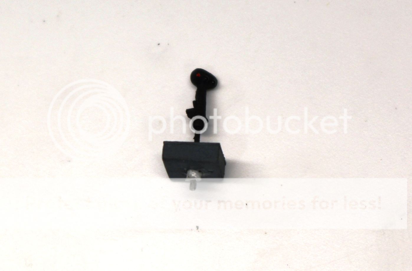
Once it was set I glued it in place from the bottom and then trimmed that little stub so the bottom of the box was flush. Here's the finished work:
With that part now finished I'm going to hold off on gluing it to the panel until the smaller details have been added first. Next up is the artificial horizon/attitude indicator.
Cheers!
Mark. -
Very impressive work. The final photo shoot looks amazing.
-
I needed to now turn my focus to the front portion of the cockpit - the instrument panel - to make sure that everything up from fit and would sit appropriately. As both Green Strawberry panels were identical in their shape and bends I used this one first as a practice. More over I needed to figure out how to bend this sucker right:
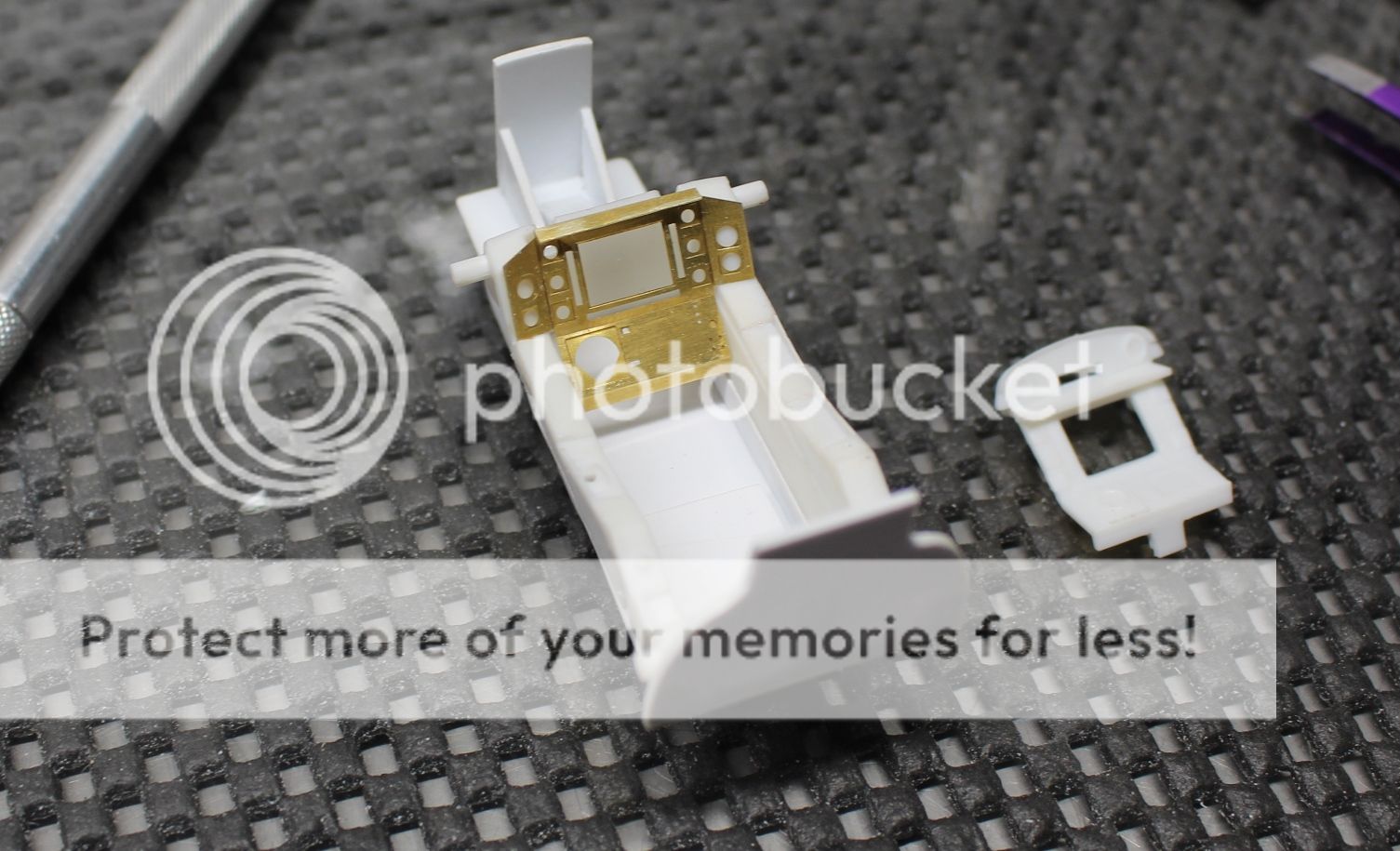
For anyone wanting to use this set, the instructions don't indicate the order to bend the panel. That upper bend is a real pain as it has to fold over past 90 degrees, and as the 'groove' in the panel is on the forward face, this bend takes a good bit of.... motivation... to get the brass to do what you want. This is why I strongly encourage starting with this one first. Anyway, here's the order I found worked best:
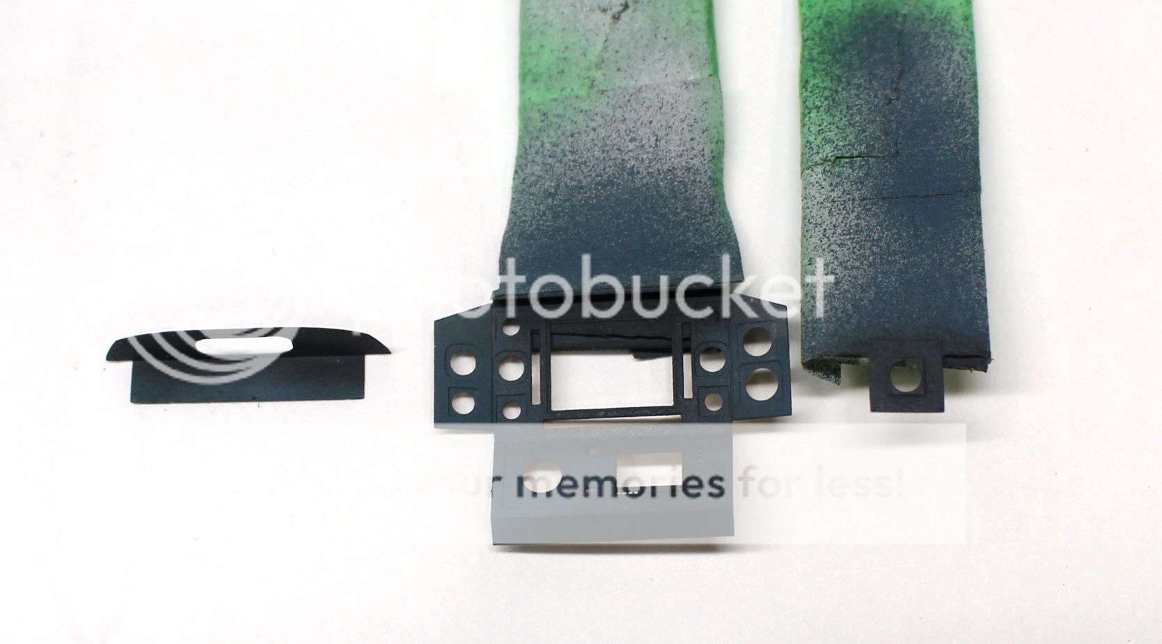
So with the practice panel done, it was time to go at the real thing. I started by cutting the parts out then using some 800 grit wet sandpaper to scuff the surfaces (where there wasn't any raised detail) to give both glue and paint something to stick to:
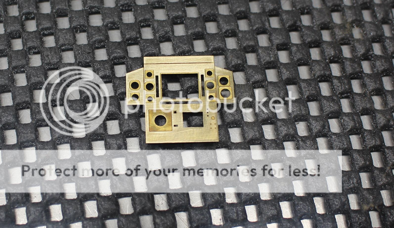
The parts were then bent into shape:
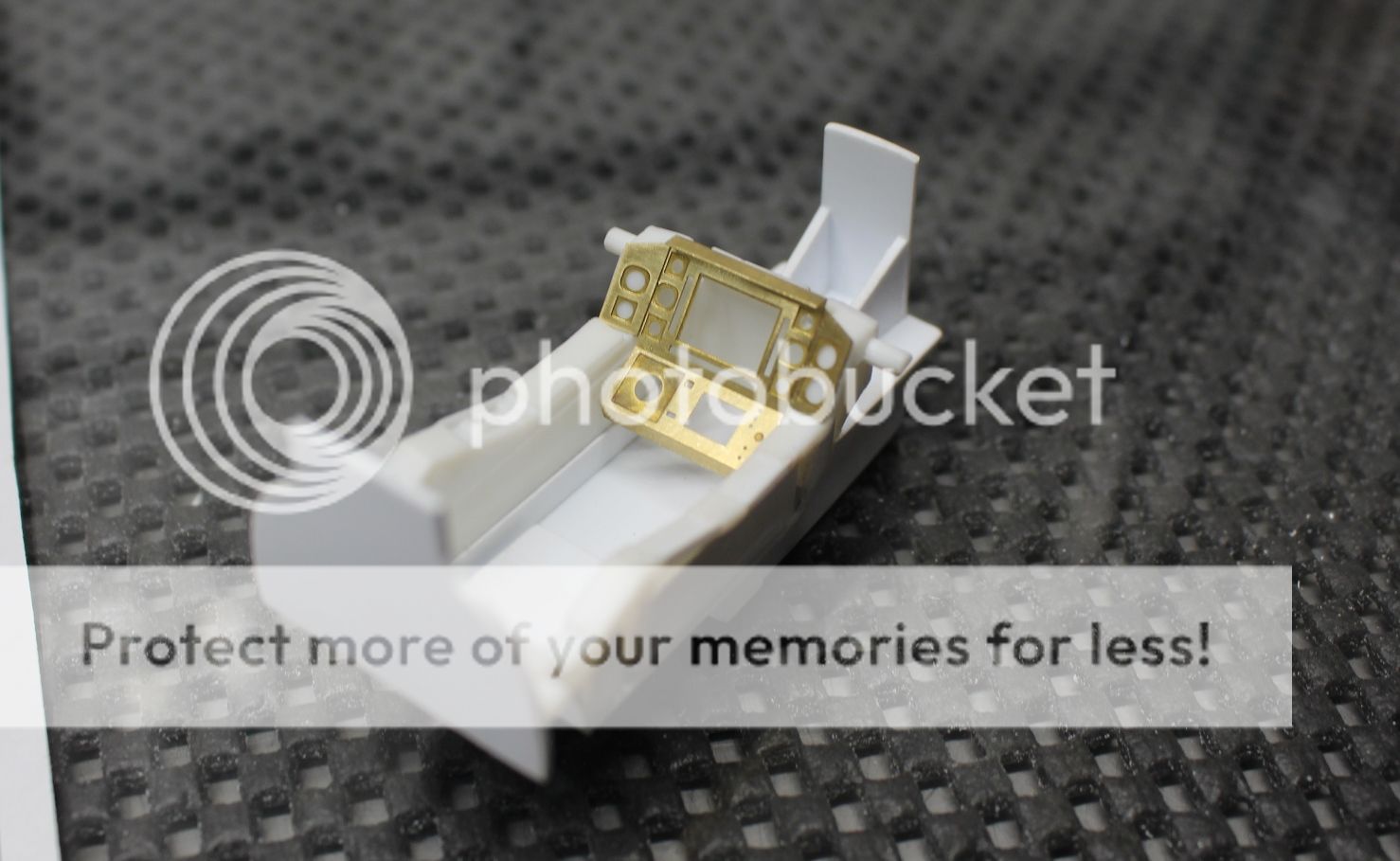
washed off with acetone and stuck to my "painting sticks" for a coat of primer:
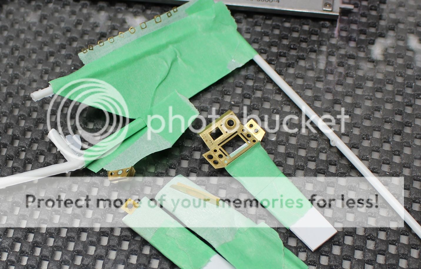
I used Alcad II primer grey as a thin coat of this stuff sticks like nothing else out there. I wanted to make sure that I could avoid any paint chips as no matter how abused the Vipers were in the series, there weren't any paint chips that exposed metal:
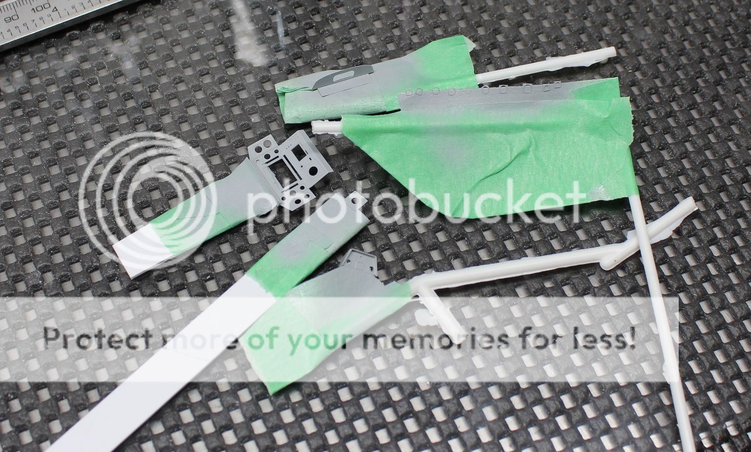
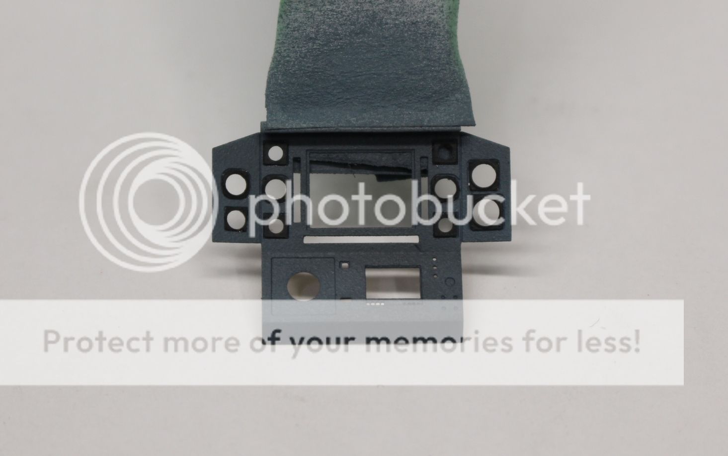
I shot the parts using either Model Masters Intermediate Blue (FS35164), or flat black (for the HUD and the instrument bezels). It was the closest colour that matched the actual colour chips. The forward instrument panels, pedestal and HUD mounting plate on the actual Vipers were with Benjamin Moore "Phillipsburg Blue" (HC 159), then given a clear coat (semi-gloss), finished with a fine silver powder overcoat. I used pastel chalks to give a bit of a wash to give the panels some depth and match them more with the finished panels in the show:
I used the 20% on lighter used areas and the top of the panels, 50% overall in other areas, and 80% in more used areas and in the shadow areas. The use of pastel chalks like this with a short cut, soft haired brush, also gives a bit of a semi-gloss 'greyish' tone that I think gave the look of that fine silver powder finish pretty closely, although this picture (without flash) really doesn't show it that well unfortunately:
The bezels were given the same treatment, and then each one was individually glued in place. I had my doubts, I won't lie. Although I like the idea of separate bezels to make painting easy, even in 1/32 the thin bezels were very delicate. Further to that, the sunken in areas for them would be painted. I was curious to see if with a coat of paint if they would still fit. Low and behold, they did! I am honestly, truly impressed with the set from Green Strawberry. Although the bezels were tedious and monotonous in gluing the 10 bezels in place, they worked out very nicely:
Once the remaining parts to be attached onto the panel are in place (the attitude indicator, joystick box, etc), the bezels will be every so lightly dry brushed to make the depth/shape visible.In all, excluding the Revell decal set, there are 4 different options that I have here:
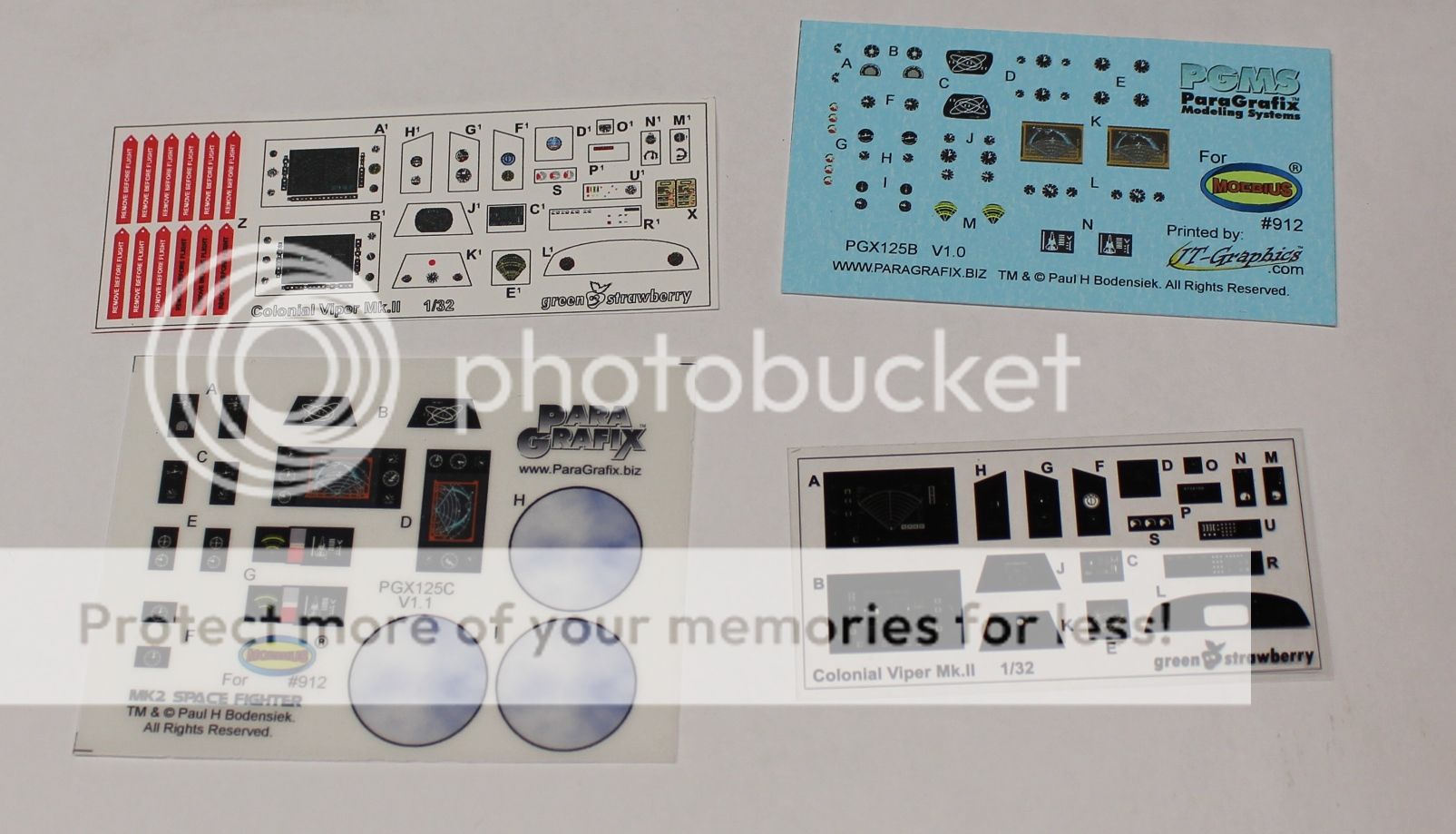
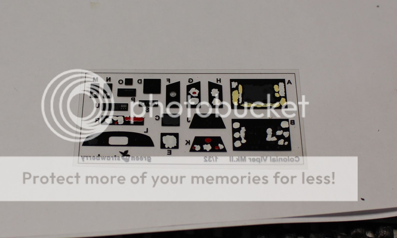
Top left is the paper print-out from Green-Strawberry.... and no. Just no. Bottom left is the Para-Grafix clear set which is meant to have backlighting. Nicely done, but wrong version of cockpit. Top Right are the Para-Grafix decals from JT-Graphics. Not a bad decal set if you don't want backlighting but still want to show off everything, but again it is for the earlier cockpit. Bottom right is the acetate film with black printed instruments. Intended to be back lit from what I gathered, I opted to go with these.
The reason for chosing the acetate film is quite simple - I can paint them back of them (like we all used to back in the day before pre-printed panels), but it also allows me to paint over the DRADIS and video screen as the Viper will be sitting without any power. So the only gauge faces visible will be the analogue ones
I went through my references and matched the colours as closely as I could. If they were white, I painted them white, if they were the glow-in-the-dark irradiated paint that was slightly yellow, I did the same. The two main screens were over painted with flat black, and anything red was matched up as closely as possible:
It doesn't look pretty from the back side, but, eh, it's late, and it's the back side. I tried it first on some of the instruments that weren't going to be used, and then went ahead with the others. From the front side I was very happy with the results:
Piece "R" for example has red needles, and when looking closely enough, they came out better than I could have hoped for:
So that's it for tonight's updates. Once everything has cured nicely I will get into the final assembly of the instrument panel. Until then, thanks for looking.
Cheers,
Mark. -
So, two part update. In this first one work continued on getting the aft wall of the cockpit cut to shape. Using a bit of cardboard paper I cut the shape out and then used this to mirror the cut line onto the 1.0 mm plasticard. Some trimming of the rear cockpit alignment pin-hole needed to happen, but it all worked out nicely:
The tiny gap between the wall and fuselage will be taken care of once the sidewalls have been installed and some (read: lots) of filler will be used to shape the rear of the cockpit:
The new piece was then glued carefully to the back of the cockpit tub and allowed to cure:

Once it was cured, the reinforcement pieces up front were added (which the seat that needs to be made later on will be installed onto). You'll also notice the 'box' that the seat sits on. If you scroll up to one of the reference pictures the front edge of that box is visible just forward of where the seat ends:
Attention now shifted to the sidewalls. If you install them as per the instructions there is a substantial gap between the fuselage halves and the sidewalls, so I wanted to try and have them glued to the actual fuselage half. To get the alignment right, the tabs on the shoulders where the sidewall sits inside of were cut off. This way the cockpit can slide away sideways from the sidewalls:
Once they were glued in along the upper lip of the cockpit, there was a noticeable gap between the side console and the sidewall:
I slid in some spacers from scrap plasticard and this forced the lower edge of the sidewall out until it mated up with the side console nicely:
The same process was applied to the other side. Once those sidewalls are cured I'll start going at the back portion to get a nice smooth rounded face like the Viper had. So, that's that! Now, before I could progress any further, some of the smaller details needed to be taken care of, so onto part 2 of the update.
-
Brett, Starbuck will most certainly be able to have normal legs! Needed for all the a** kicking she does, right? It is a bit of work to get it "right" (as close to right as I can get it), but it's a lot of fun. I continued with where I left off by starting out with the rear lower deck of the tub. Again, it's all done using 1.0 mm plasticard. The two pieces were butted up and sanded round on the exposed joint:
From there it was the floor followed by the angled plate just forward of the rudder pedals:
So now that we're back at having a tub, I opted to fix the nose gear well in place as it would be easier to get the angle right and build up the nose gear well again. I added an even further extension rearward while I was added to give a little more room in that well for the gear. The extension was added by using some spare plasticard and then a little bit of 0.25 mm plasticard cut at an angle and glued inside the gear well to cover up the seams. Let's call them stressor plates to sound technical:
The tub and nose gear well were dry fit into the cockpit half to make sure everything still fit right, which thankfully after all of this it did:
Next up I dry fit the sidewalls (p/n 21 and 22) to make sure that everything still fit just right:
They fit just fine but there is a gap in the rear area between the sidewall and the fuselage half... and just in case, Moebius did us a favour by visibly casting the p/n's on the INSIDE of the parts for all to see....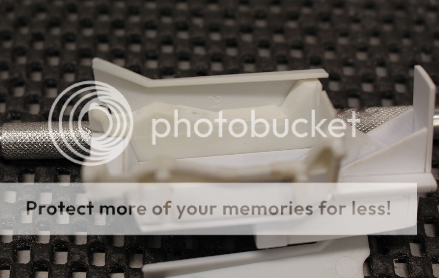
Right.... anyway, the sidewalls have a curve to them and a bit of work needed, along with a very thick upper frame that isn't right. So as I've gone this far, I'm going to scratch up some sidewalls for the cockpit. But, the next step is going to be to build the rear cockpit bulkhead and work on the floor details first:
Getting there slowly! Who knows, maybe by the end of the weekend I'll actually have some paint in there so that we don't all have to get a tan from so many white parts.
Cheers!
Mark. -
Brett, GREAT reference! After some brainstorming on how to go about the cockpit, I didn't want to throw the baby out with the bathwater as it were and toss the cockpit and start from scratch. A number of problems do exist with the kit cockpit, but then again, this isn't a three digit 1/32 purchase from major model manufacturers. So, sometimes you have to roll the hard six... I decided that there is still enough good detail in the cockpit to try and salvage it.
The first step was to reinforce the addition of the mount for the gear well. I took some scrap plasticard and glued them together to make a wedge shape that will hold the forward half in place:
Once in place and the glue cured, it was time for some plastic surgery. I started by cutting the floor (and the mount for the nose gear well) at the firewall. From there back I cut away the cockpit floor:
The seat and the floor mount for the stick and the panel will need to be redone as well so they were next to go. I cut as far back as the two studs for mounting the cockpit tub into the fuselage... effectively leaving me with a firewall and two sidewalls:
While at this point I went ahead and cleared off all the instrument areas and cleaned up some of the edges to give a sharper look to the cockpit structure:
So now with the sidewalls ready for PE parts later on, it was time to figure out exactly how to go about this whole thing. As I was looking at the reference pictures I found a panel line in the cockpit sidewalls (visible in the second reference photo from my previous update). If I added this extra section that would give the cockpit enough depth (it's about 3.0 mm) and still have room for the nose gear well (albeit with a little modification). So I added some side wall supports, a spacer, and then glued in a 3.0 mm tall strip of 1.0 mm plasticard to the bottom of the sidewalls. The forward part is cut at an angle, and the same angle will be cut into the gear well:
That spacer I mentioned was to add the look of that lower portion of the cockpit sidewall in the reference picture so that I ended up with that raised edge look. Here is the finished piece in a fuselage half which now at least looks like a properly sized up cockpit tub for the Viper:
With the kit panel piece dry fit into the tub, sitting on some plasticard, there is definitely more room for feet and rudder pedals now:
Once dried the next step will be gluing in the cockpit floor and rear bulkhead/wall and then building up the cockpit from there.
Thanks for looking,
Mark. -
What can be said that hasn't been already? Brilliant work there Brett!
-
Testing your patience maybe, but WOW is this one impressive bit of work. As for the lighting, well done. Not too often you see just the right amount of light and a proper bit of diffusion to give 'the look'. I can't wait to see more!
-
Brett, the BoP is an impressive build good sir! Fantastic aging and weathering applied with a great combination of rich and subtle tones.
-
Right.... so, the cockpit.
The steps seem pretty straight forward from the kit instructions.... skipping the figure, steps 5, 8a and 8b complete the cockpit in the kit: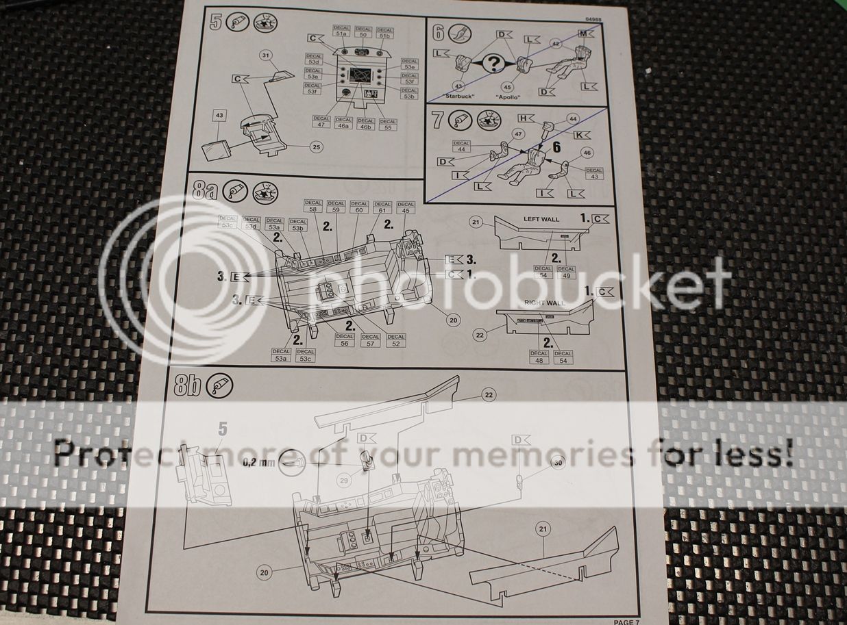
Although the kit does provide a cockpit with the figure, the details are fairly soft and limited in their detail. The approach of painting with decals for instruments will work no doubt with a figure and closed canopy. With an open canopy, and in 1/32 scale, there is a lot left to be desired. As such I picked up two aftermarket sets as listed in the first post.
There are typically two cockpit designs recognized in the BSG series for the Viper Mk.II; the early and the late cockpit. Externally the Vipers were nearly identical in every aspect (aside from one episode where Starbuck came back with a new Viper and rivets in the canopy frame). Using the actual prop Viper that was auctioned off some years back that was modeled as Starbuck's Viper as my reference I wanted to make sure that the cockpit was correct.
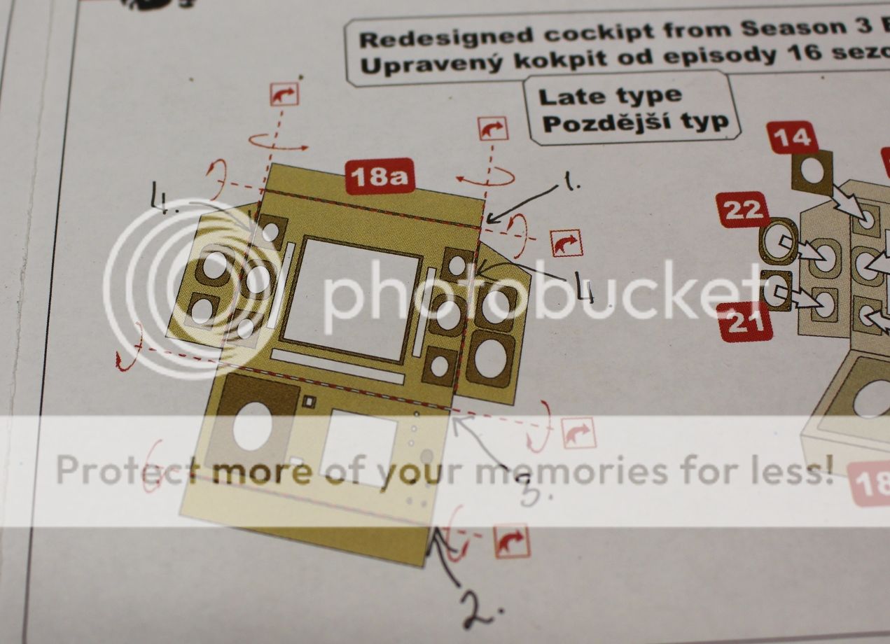
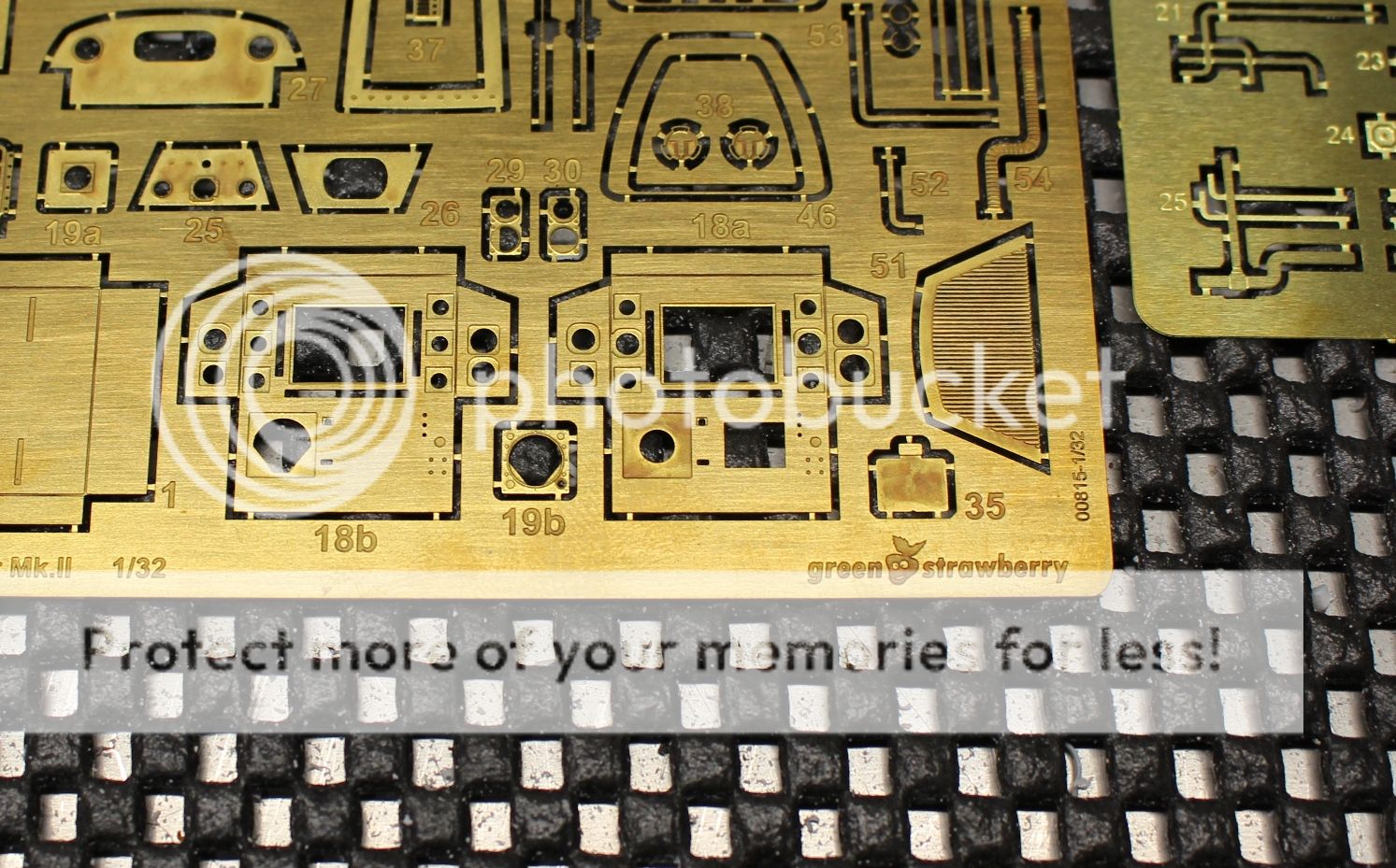
The two sets shown here offer a multitude of additional details (for both back-lit and non-lit cockpit instruments):
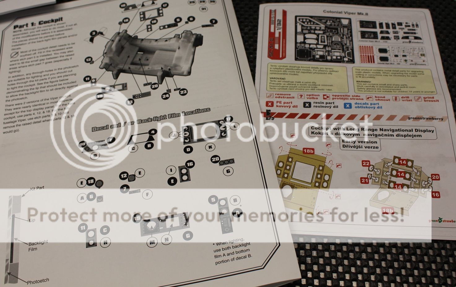
The Para Grafix set (on the left) offers one cockpit (the early one) and the set from Green Strawberry offers both:
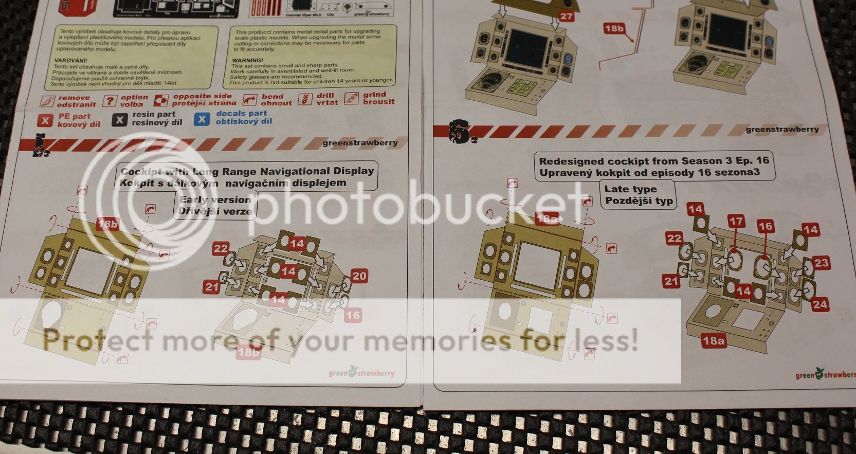
These guys really did their homework as it was season 3 episode 16 where you see the new cockpits being filmed. Now don't get me wrong, both sets are very well made with fantastic details as you can see here. First the Para Grafix set: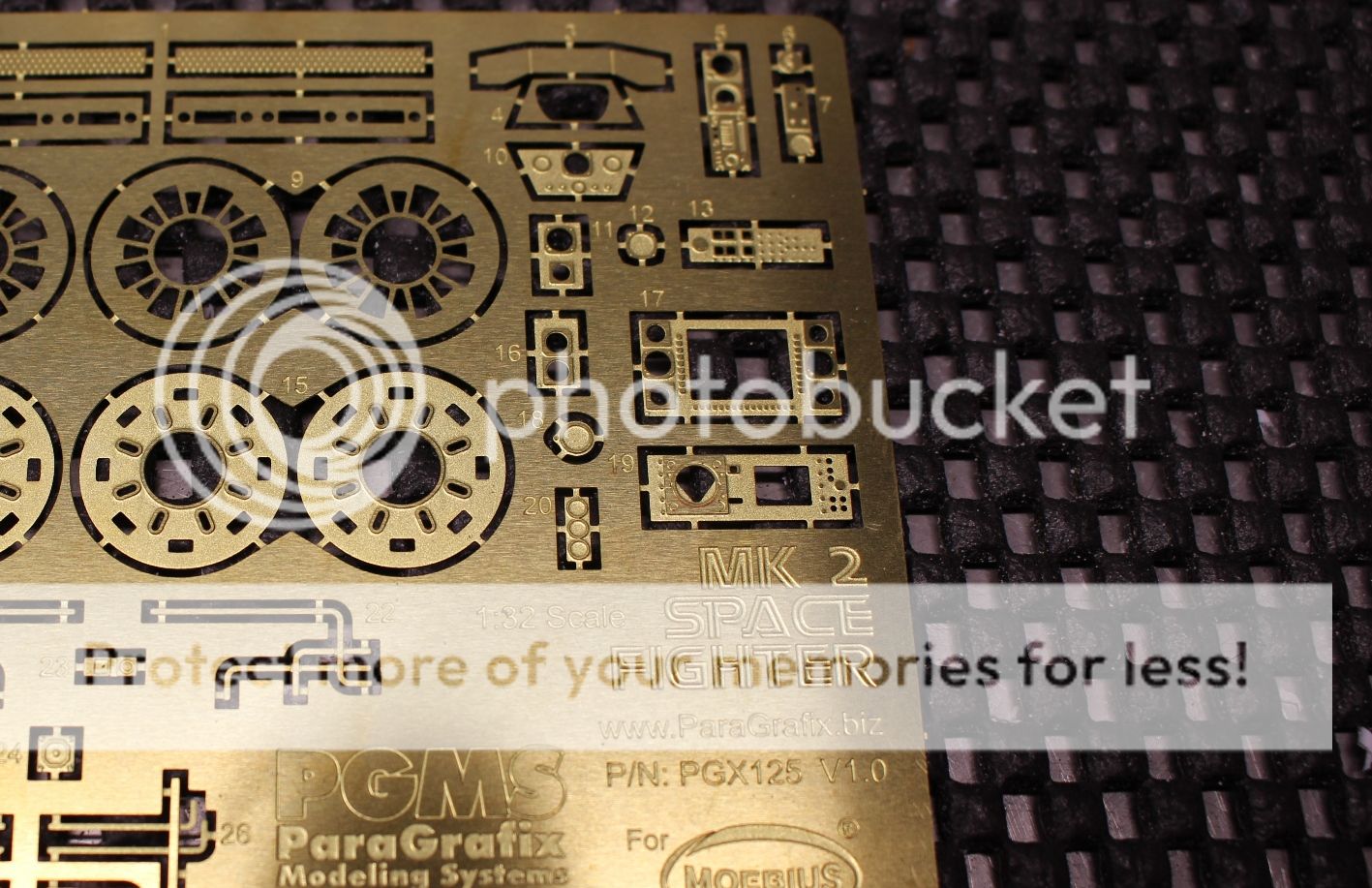
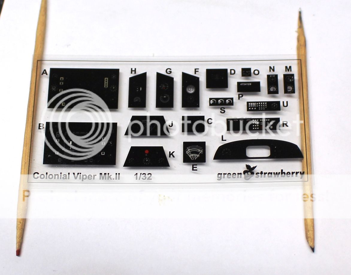
And here is the Green Strawberry panel:
The easiest way to distinguish between the early and the later cockpit comes down to the area just in front of the joystick (it is literally a joystick used for the props). The later one had a smaller floating ball to show pitch and attitude where the early one had a sweeping gauge. Further to that the early one had 3 small pressure gauges just forward of the stick and the later one had them deleted. So which one to use? Well, here are a couple of great shots from Aaron Harvey who shot pictures from the aforementioned auction:
And here's a top down shot including the seat:
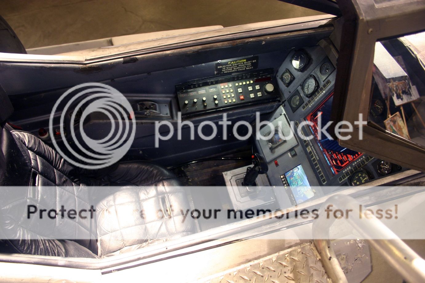
As you can see from the photos above, the Green Strawberry set offers the later cockpit. Alright! On the right path! That is until I put the instrument panel (p/n 5) from the kit into the cockpit tub (p/n 20)...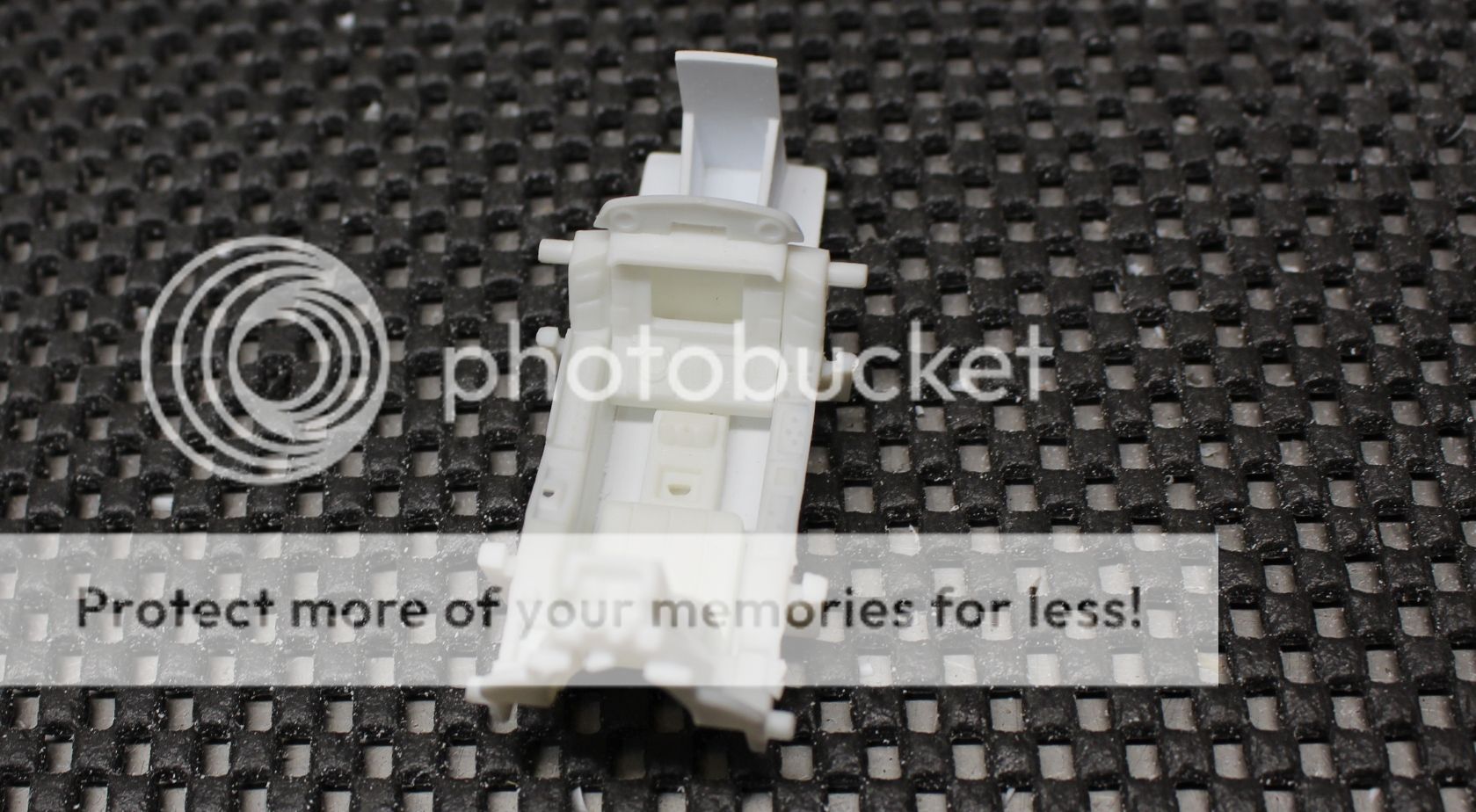
So.... how do I fit rudder pedals into there? Doing some measuring up, the cockpit is way too shallow.... remember that open cockpit floor that I closed off? Ha, well, that's come back to bite me.
The open floor gave the look of a deeper cockpit tub, and allowed the figures legs to drop into them making it look deeper. There are a few other smaller details that are also bothersome. The cockpit seat isn't anything like the actual Viper seat, and there is a lot of open space to the back of the cockpit wall that needs to be reworked.
I had two options... ignore this and carry on, but, I mean, there is literally 2.0 mm between the bottom of the panel and the cockpit floor without a figure, and leave myself wishing I hadn't taken that route... or option two, remove the floor aft of the firewall of the cockpit tub, rework the floor in the nose box, giving enough room to have a convincingly deeper cockpit floor. This also allows me to correct a few other items.
I could always just completely scratch build the cockpit tub and seat and start with a clean slate, but then it's a matter of needing to get the right alignment tabs in the right location and that presents a whole other set of issues. So, I'm going to think about this for a bit, and by the next update I should have something to post up about the cockpit issue.
Cheers!
Mark. -
7 hours ago, phantom said:
Thats ok, you can keep going after it ends.
Definitely something to think about Phantom. Let me sit on that for a few days as I just had a bit of a hang-up (post after this one) that may be delaying things just a bit.
22 minutes ago, Brett M said:Nice work Mark. That's a huge improvement over what Moebius thought was "good". Looking forward to seeing more work like this as you progress.
Thanks Brett. This little bit of an improvement I hope will go a long way, and now that the box for the nose gear is complete, it is time to move onto the mains.
The engineering behind this kit leaves me a bit baffled. The parts were taped together in order to get a good idea of what needs to be done with the mains, and I have to say.... in some ways the jig-saw style (or rather slide-and-lock) approach makes sense in some ways (I guess), but really leaves me to wonder what in the frak they were thinking (there, I said it hahaha).
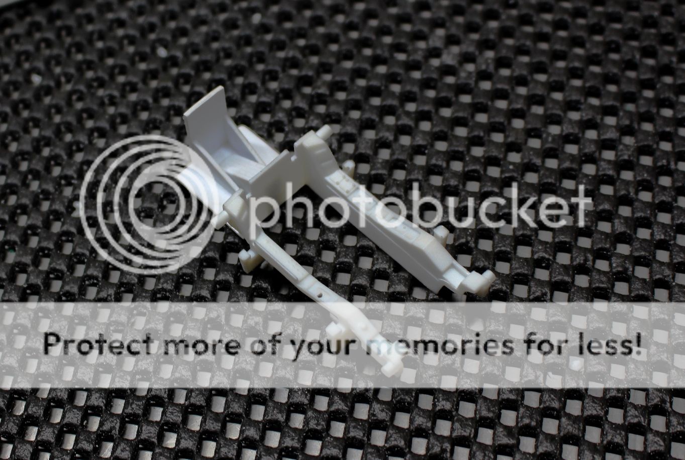
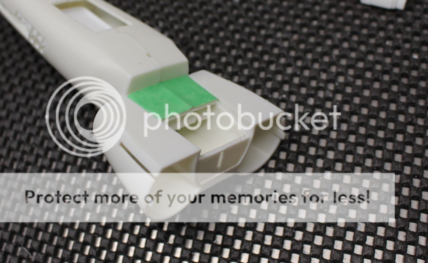
This picture below shows the port wing (p/n's 4 & 3), along with the port and starboard engine intakes/grills (p/n 8), with the forward fuselage components and belly piece (p/n 9):
So... yeah.... anyway, rather than complain about the very strange engineering of parts that leaves a number of seam lines very difficult to get at to fill (and there will need to be lots of filler), let's just get into it.
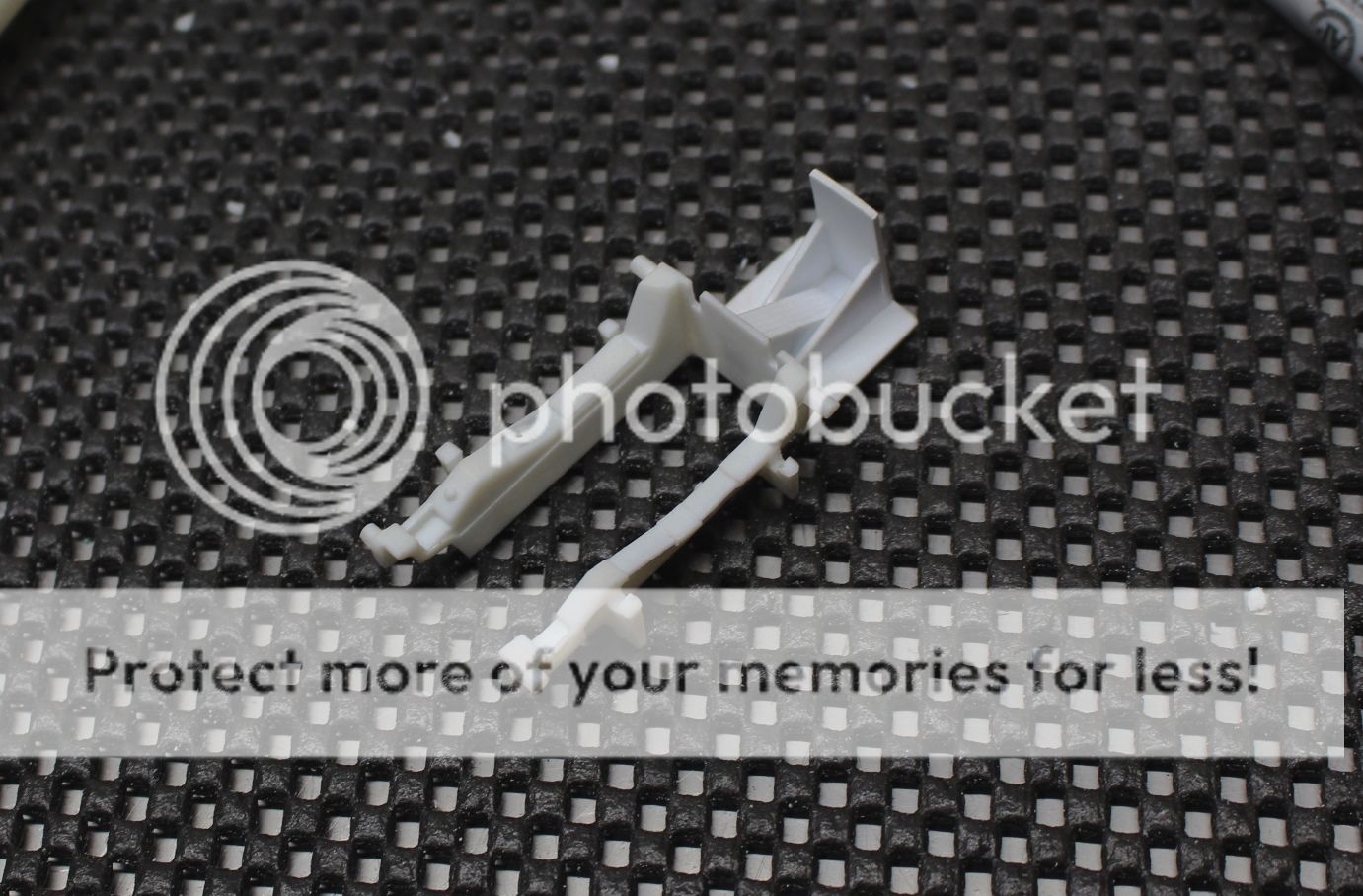
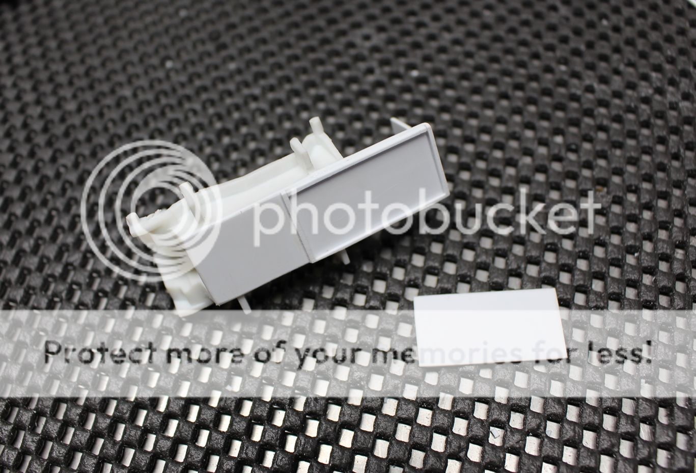
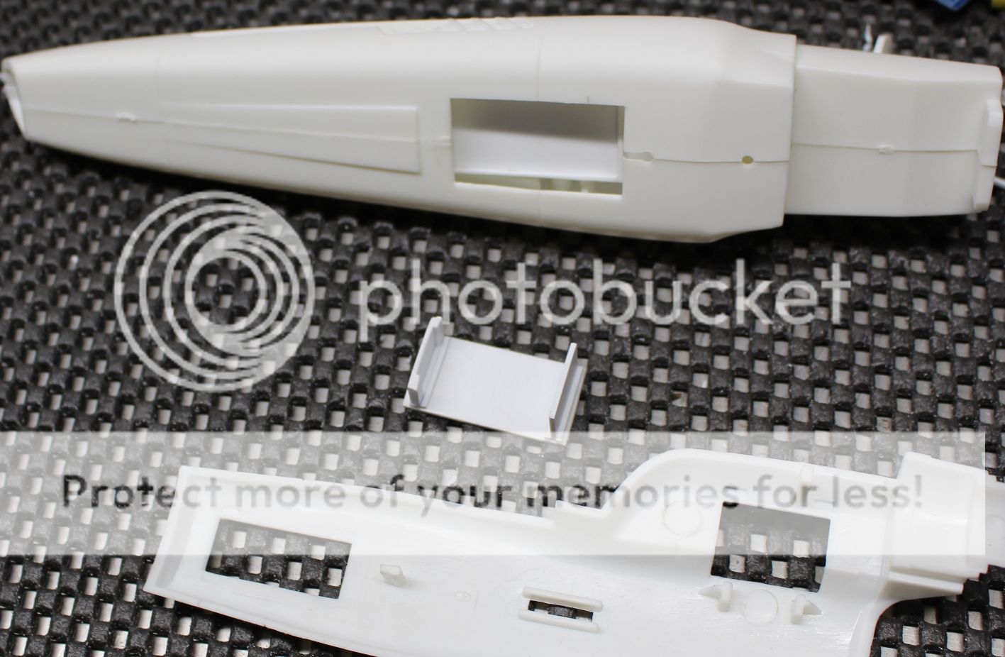
Removing the wing and working with just the aft end of the model, there was a lot of plastic that was going to be removed. First step was to get rid of the lower tabs protruding from the center rear of the two fuselage halves:
And here is the same area cut cleanly to open up some space:
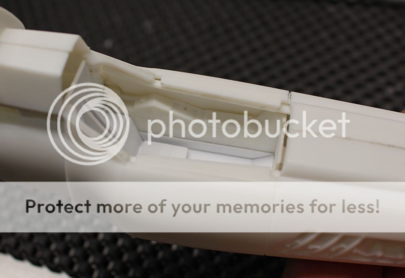
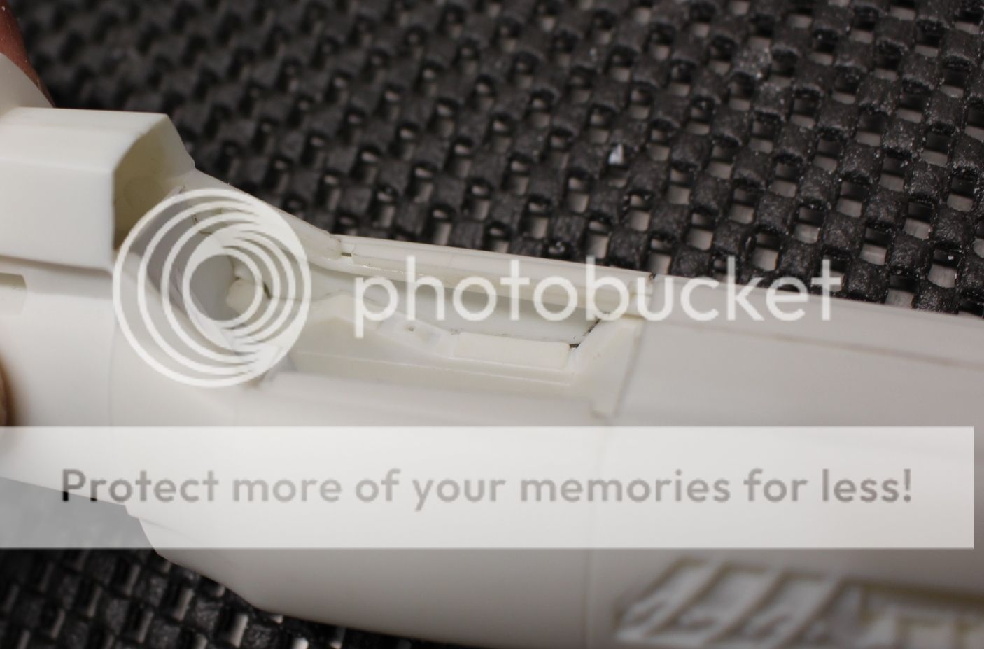
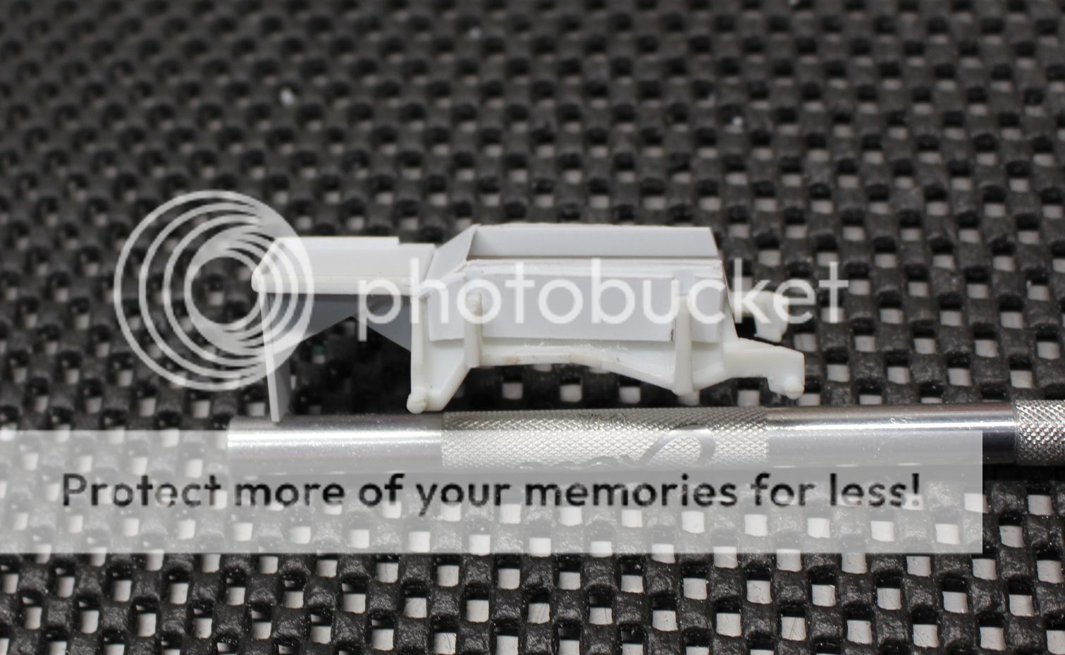
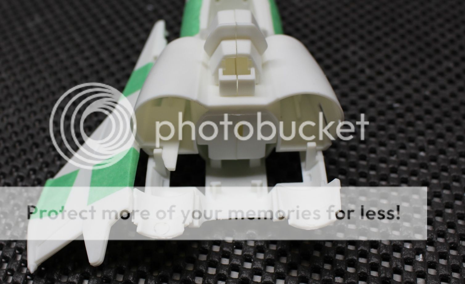
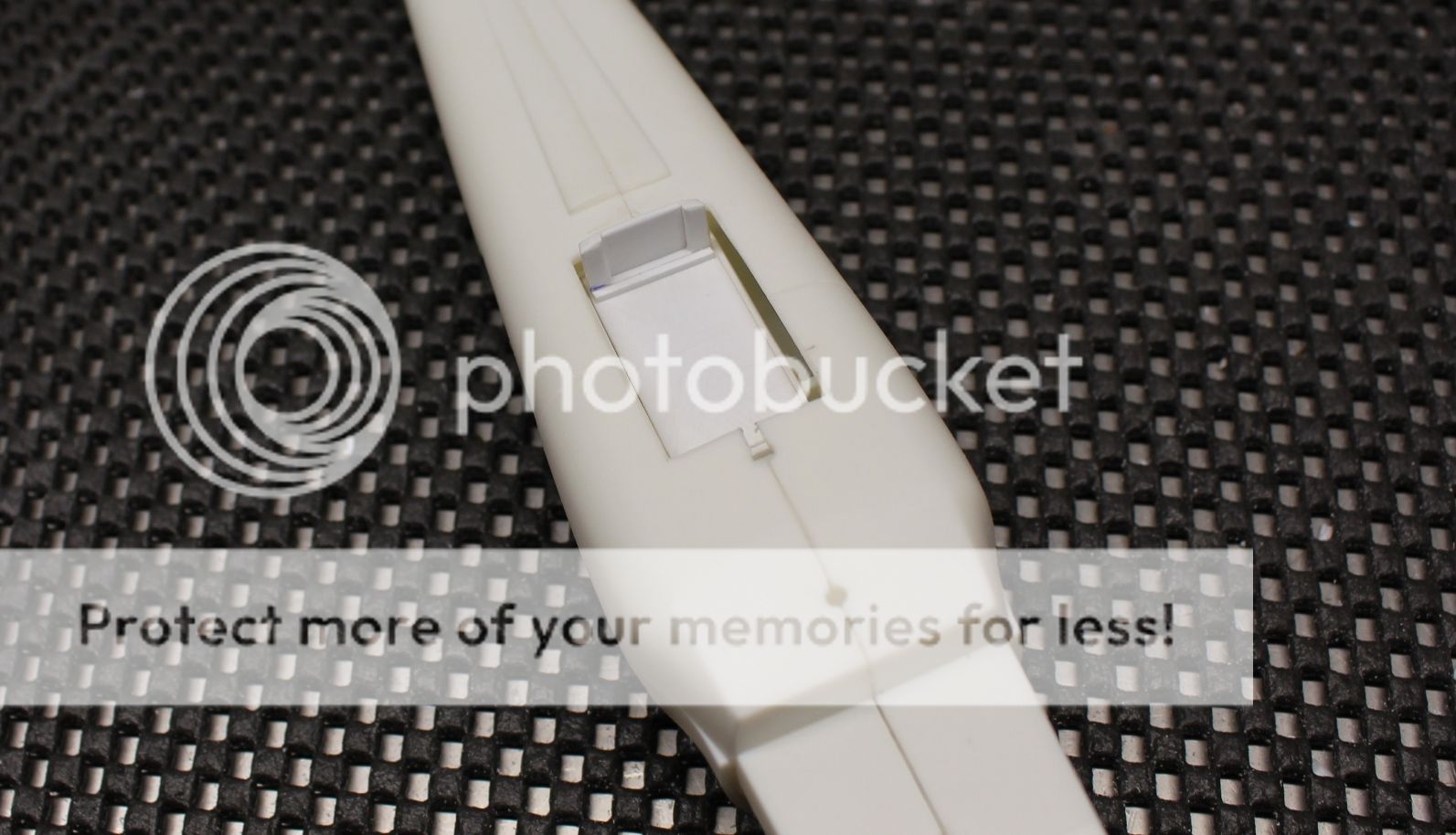
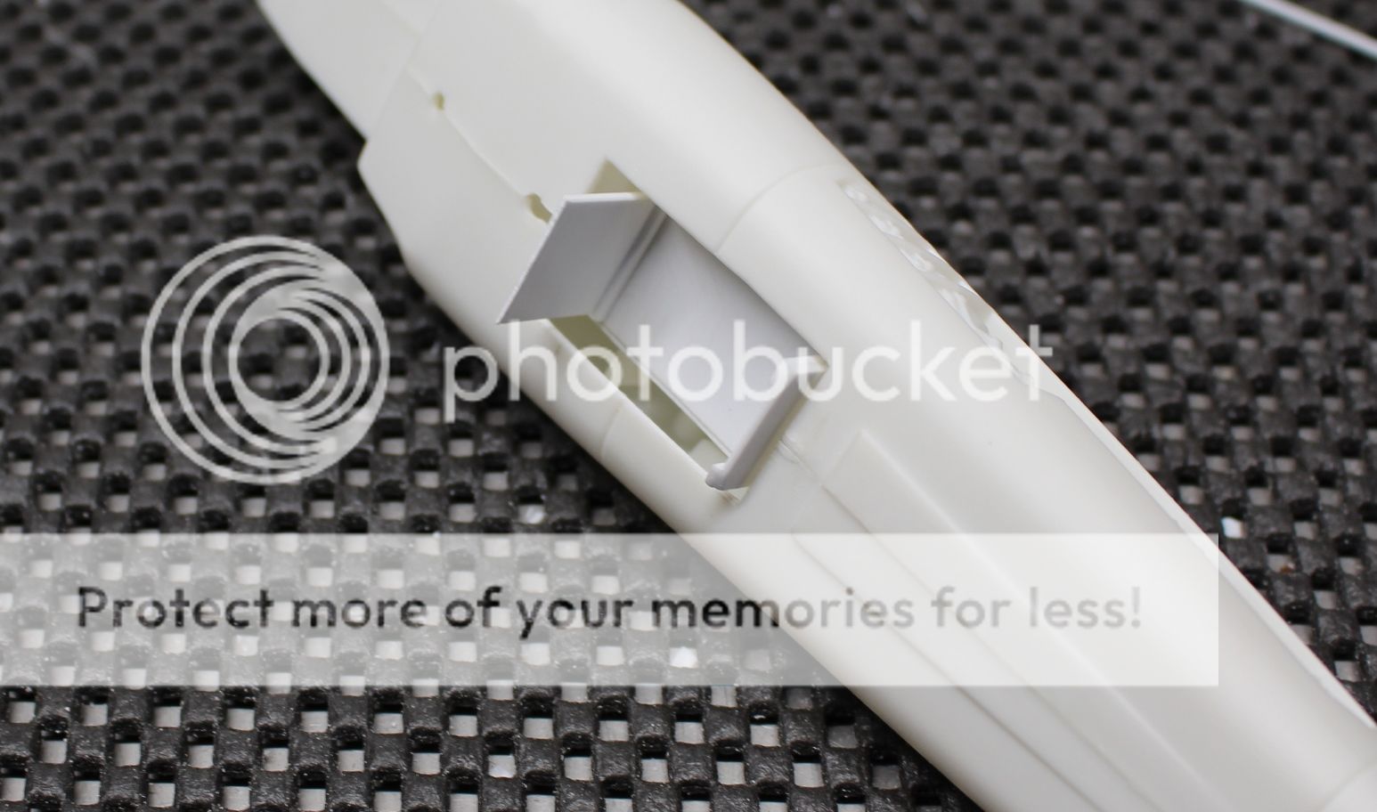
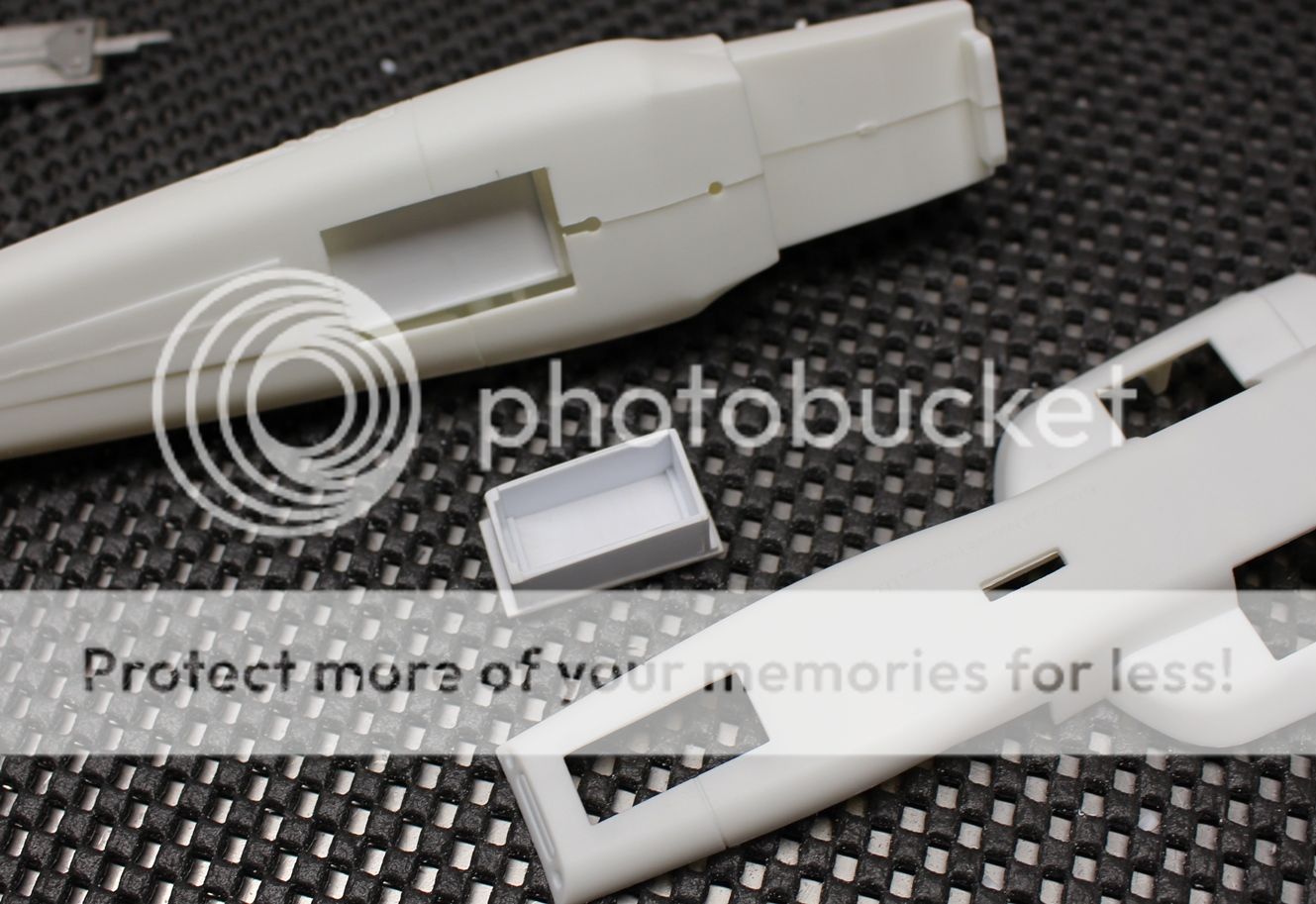
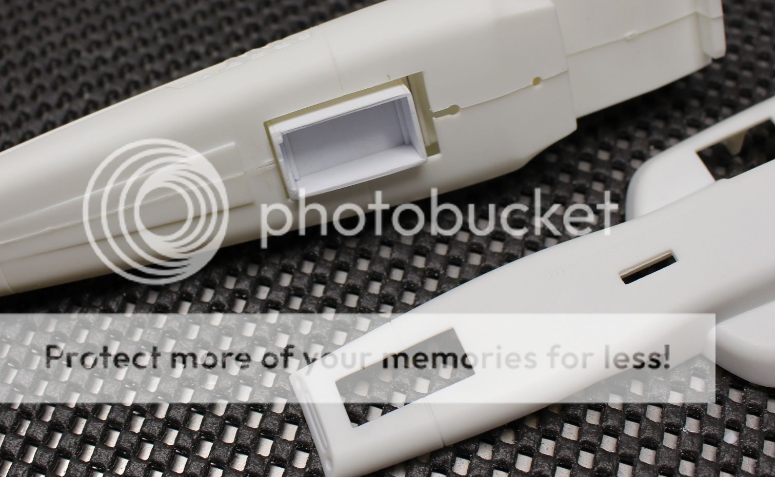
With that removed I sized up I went back at p/n 8 in order to remove more plastic around where the gear legs would be. To be more exact, you can see in this picture where the mains are fixed at the gear 'knuckles' and although there is a sound design in the sense of providing a solid place for the upper portion of the 'knuckle' to rest against p/n 8, there is absolutely no way the gear would be able to retract. Combine that with being able to see completely inside the aft portion of the model from outside of the open gear wells, it needed to be constructed in the same manner as the nose gear box:
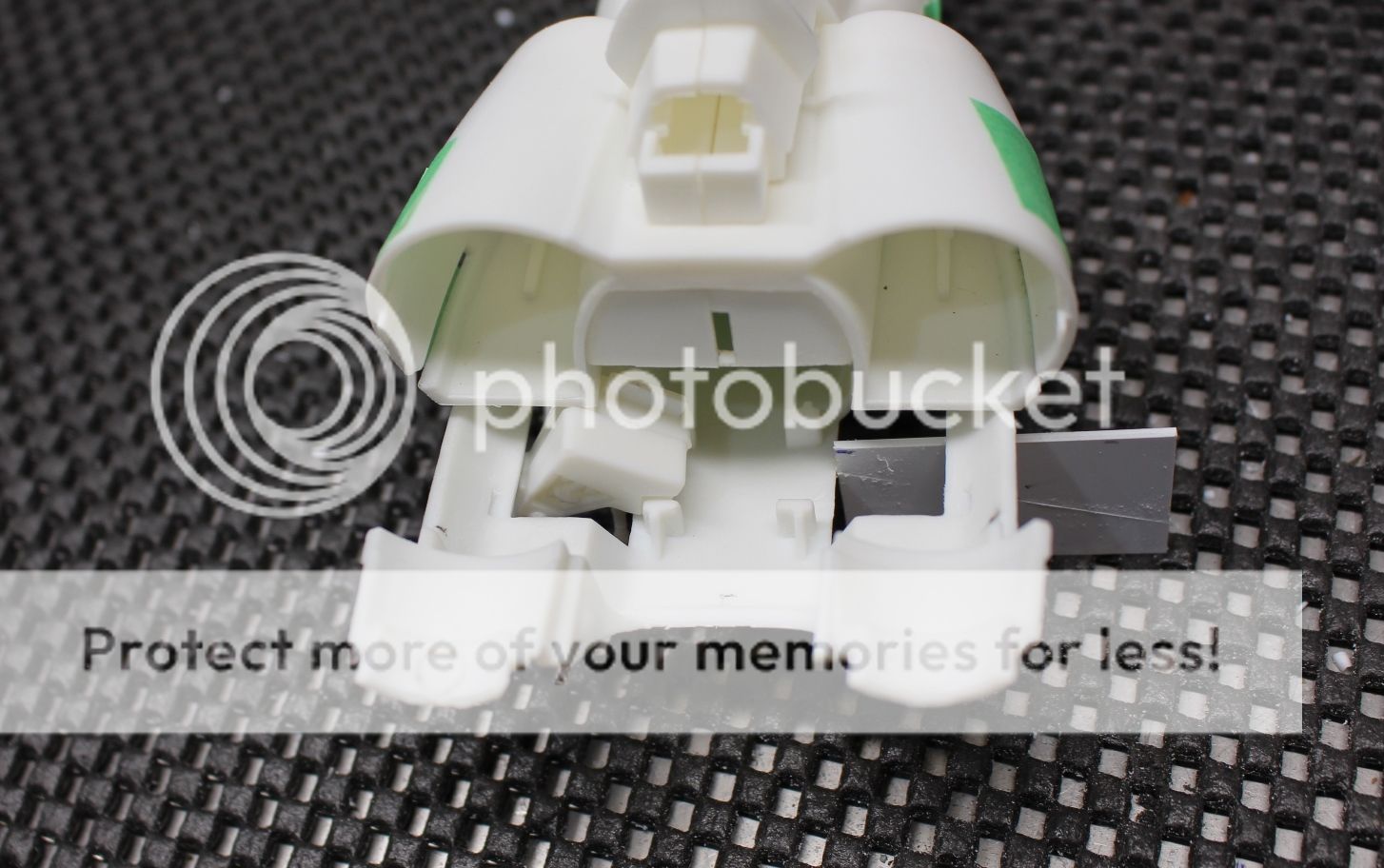
Before cutting into p/n 8:
And afterwards:

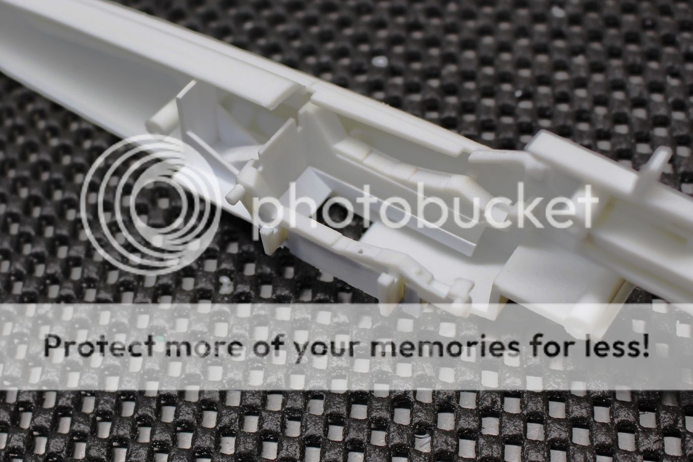
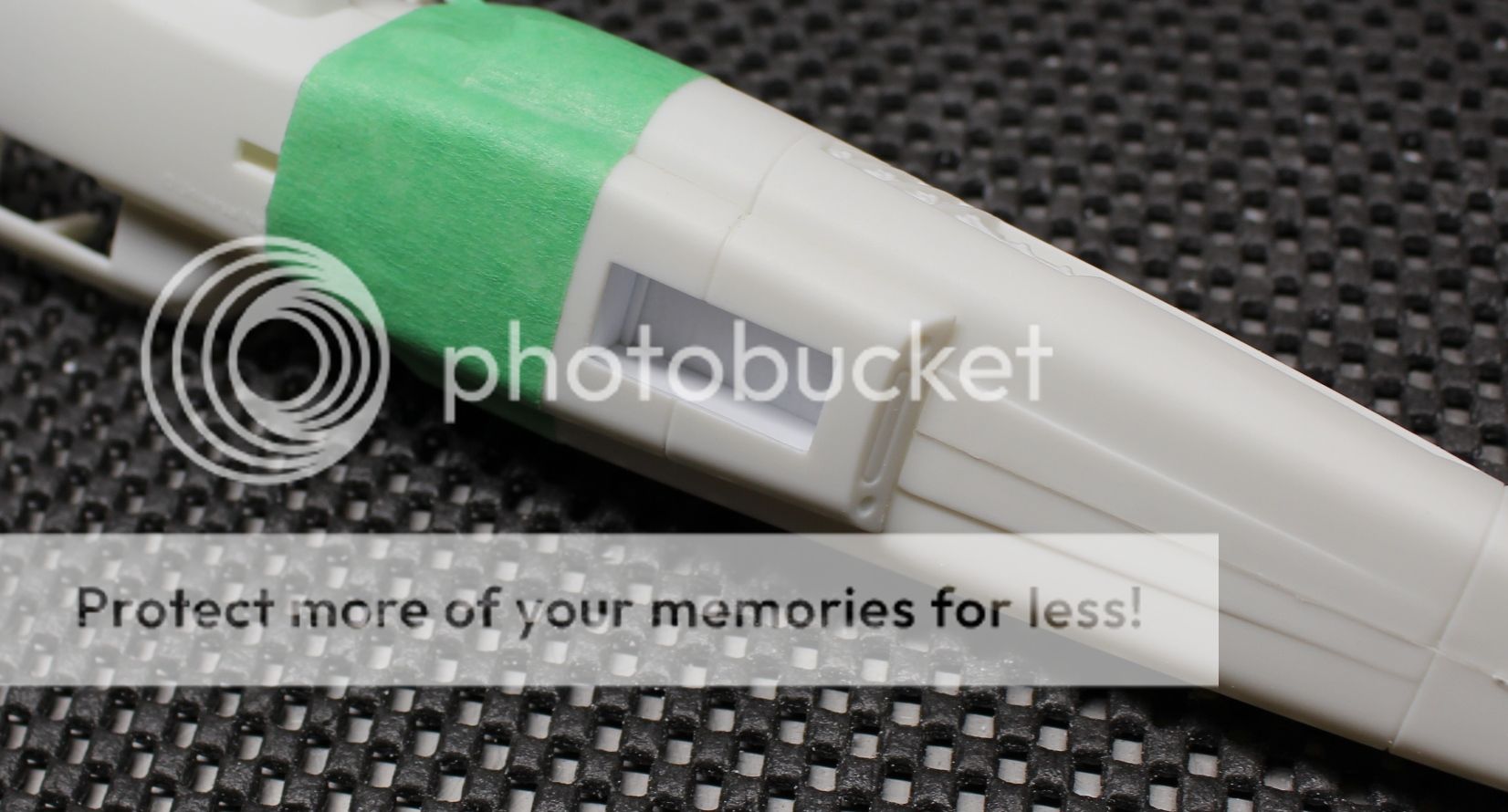
So now that everything was cut open I was about to start laying in the parts for the box. There was one major issue (and it comes down to the engineering of the kit). For me to achieve a proper fit, without gaps or weird angles, p/n 8 needed to be firmly glued to the two fuselage halves. Otherwise, due to the slide-and-lock approach to the assembly of the rear fuselage the box assembly would get in the way. So, the parts were cleaned up, a quick drawing put on paper so I wouldn't forget, and the next thing that needed to be done was the cockpit in order to be able to glue the fuselage halves together.
So this is the part were we deviate from the building instructions of the kit and start assembling the model in the traditional model builder fashion... in whatever bloody order seems to make more sense, hahaha.
Okay, part one of tonight's update is done... next up... problems!
Mark.
-
19 hours ago, phantom said:
Very nice, you should transfer this thread over to the "The ain't real" group build.
Phantom,
That is one amazing GB for sure. Lots of very interesting works (both sci-fi and what-if). I was thinking of initially asking to join that GB and post in there until I saw the date. There is no way this one is going to be finished by then. The usual stuff like home life (kitchen renos), work and the like always take the priority, so this one is a bit of a plug and play as I go along.
Cheers,
Mark. -
Madhatter,
Thank you kindly. There is just something about the way the Vipers look. From the original Viper, to the Mk.II, and onward... the conceptual designs people have made keeps the Viper series true to form - one heck of a fighter. The combination of 20th century look and feel without over-complicating things with tech that isn't believable, even though it is sci-fi, just makes this model build that much more fun.
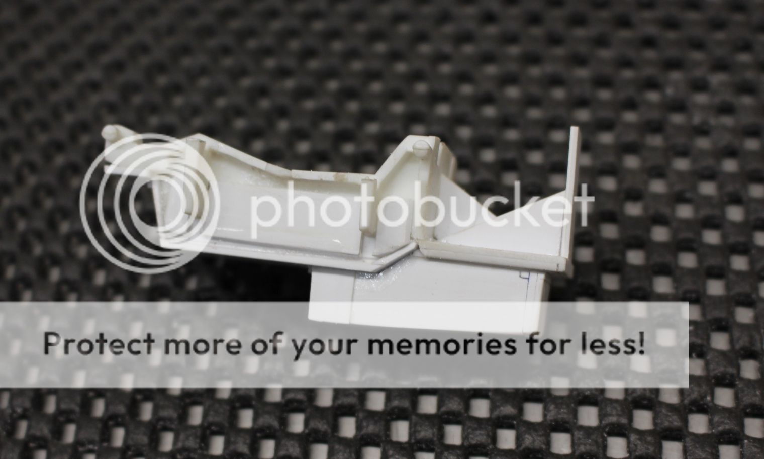
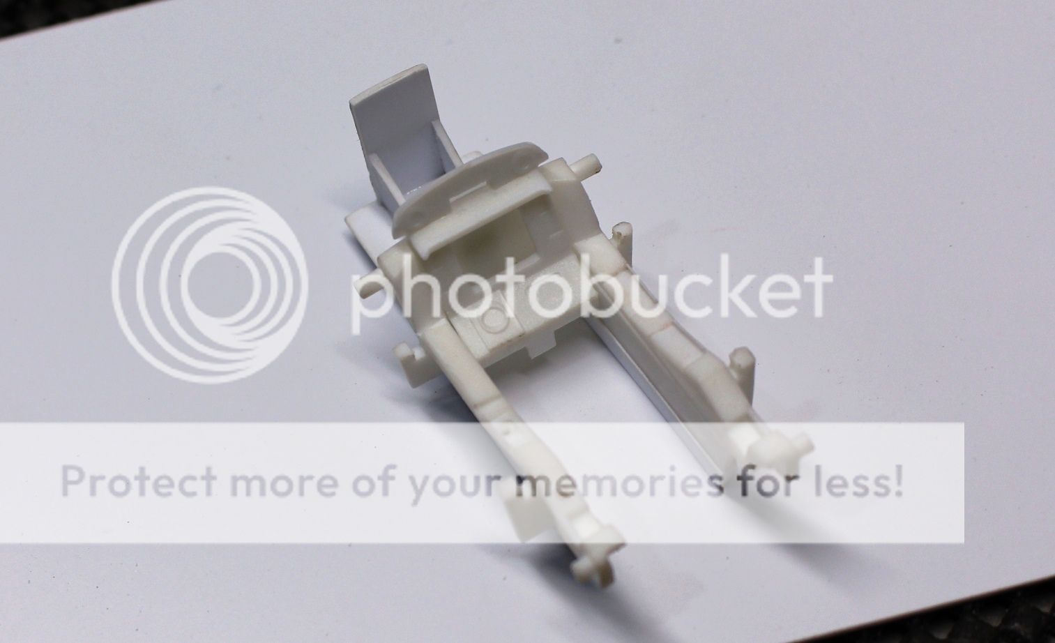
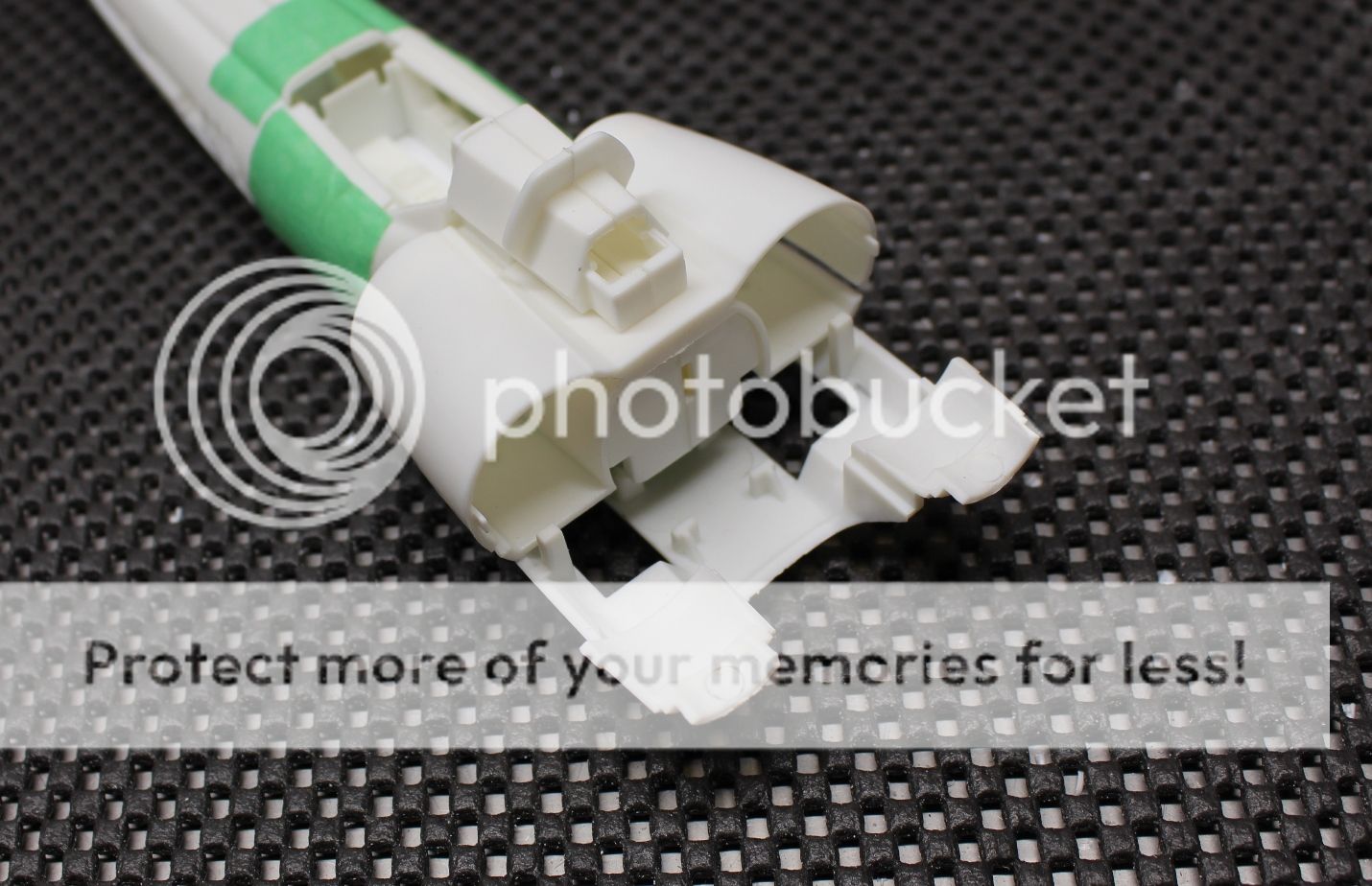
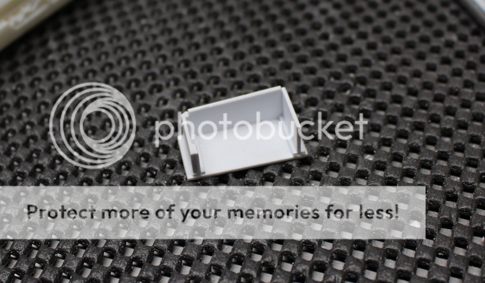
Work continued with the gear well (and I won't lie, I had the BSG soundtrack playing in the background). The base piece attached to the cockpit floor from the last update had that outer lip added to it. This was made to fit the upper base plate for the gear well:
I started construction with the forward bulkhead. Knowing I wanted the forward "knuckle" of the landing gear to mount to this, I used 1.0 mm plasticard and cut out the approximate width of the main piece of the gear to have somewhere secure to mount to. Then I put a second 1.0 mm card behind it:
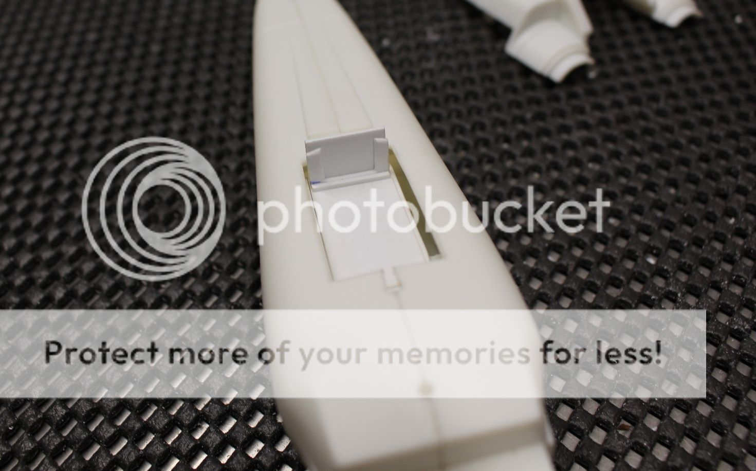
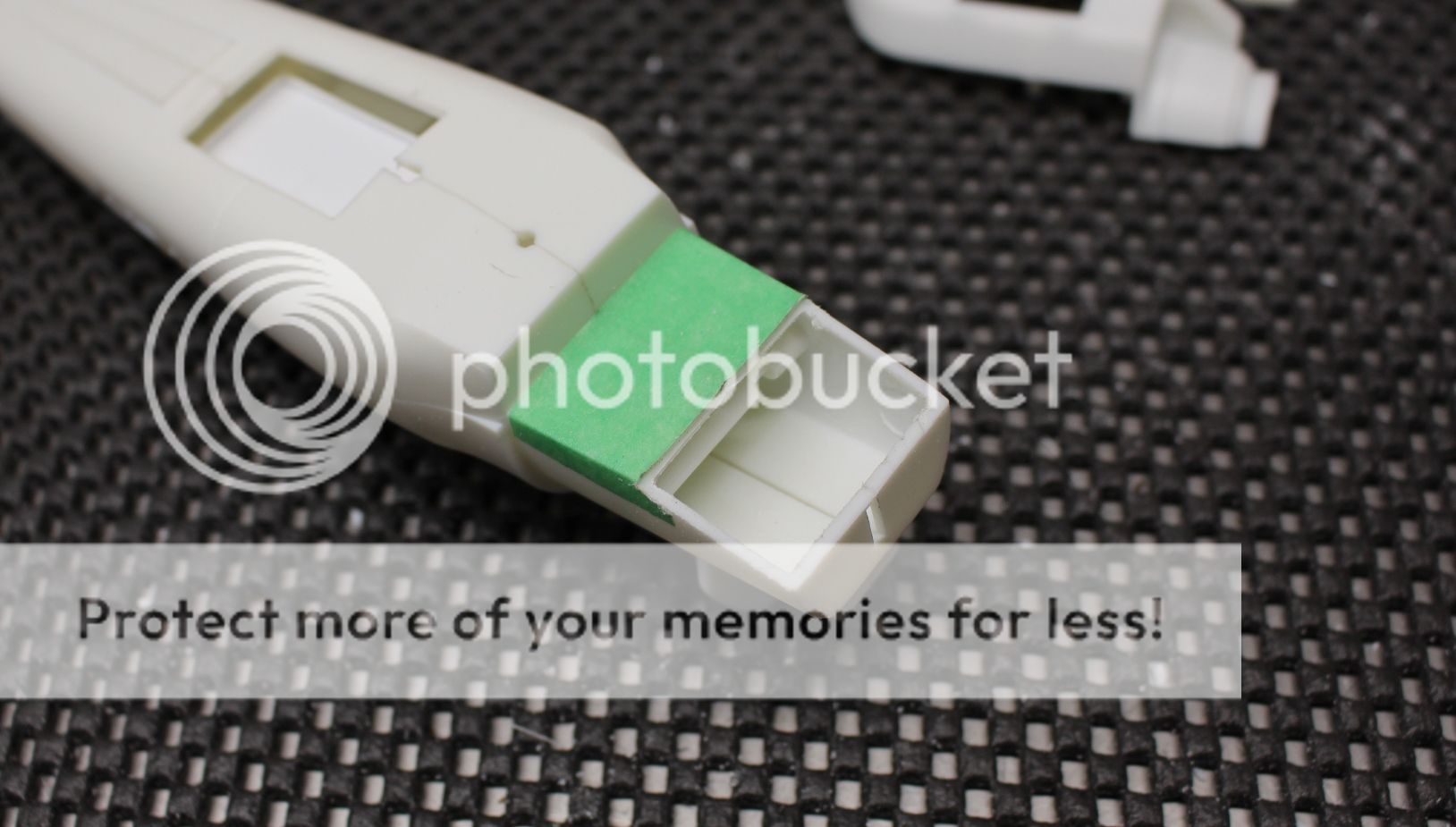
This was then shaped to match the opening on the lower fuselage piece (p/n 9) so that it would conform as closely as possible:
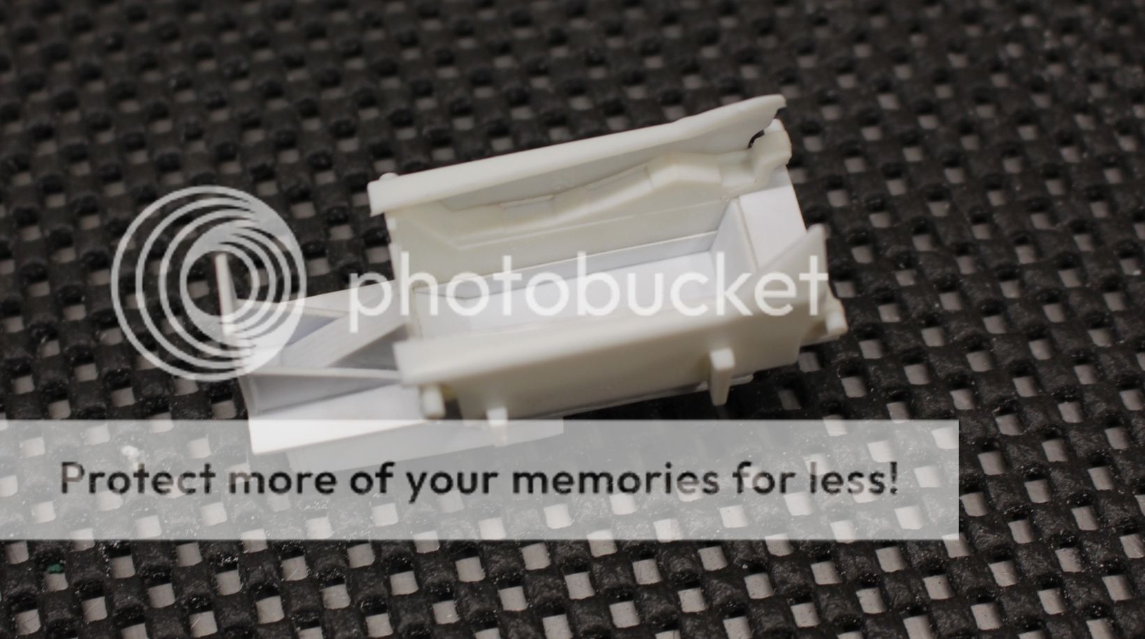
And here is p/n 9 dry fit into place:

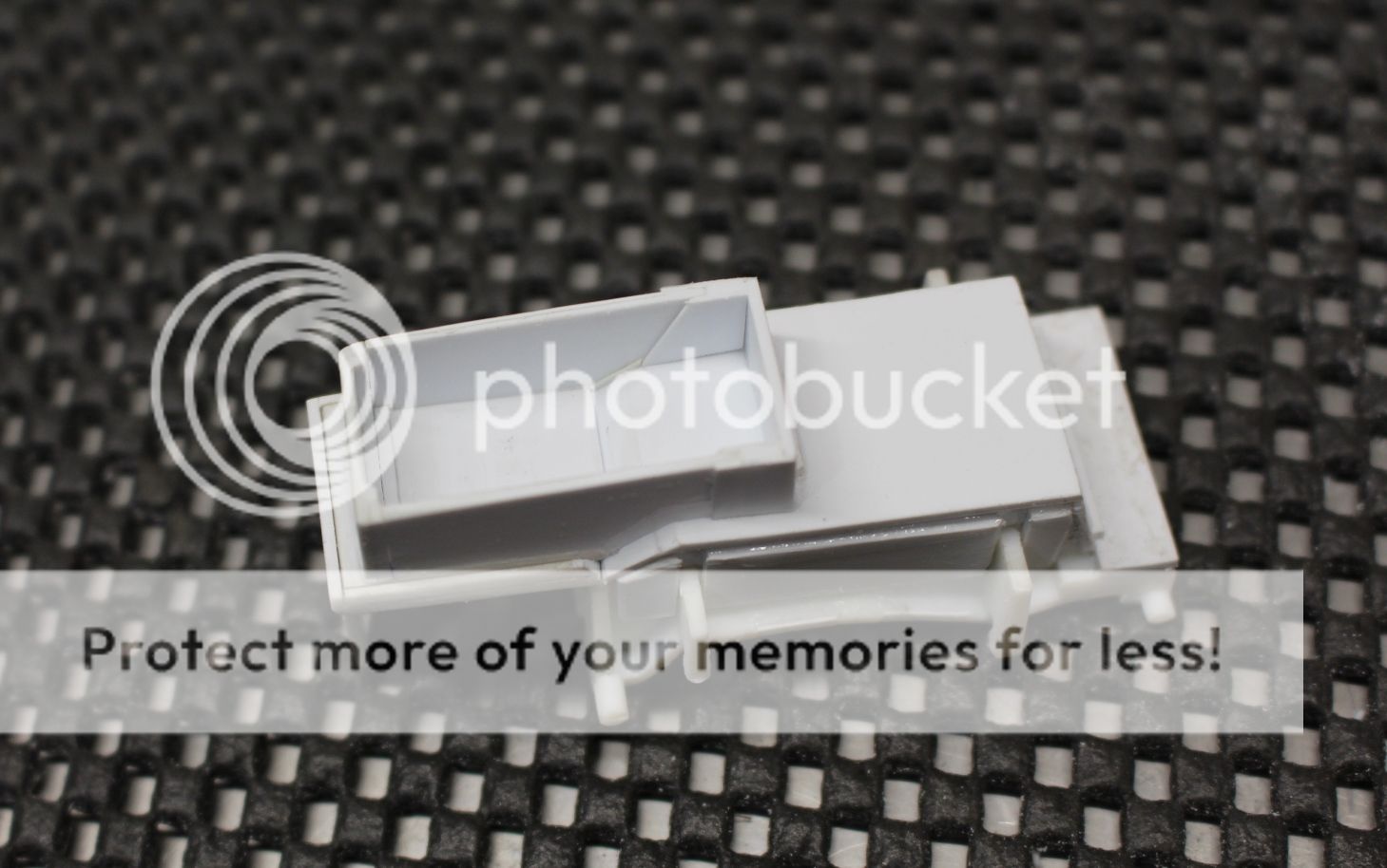
Although the forward bulkhead will be flush with the opening of the gear bay, there is no physical way the rest of the gear strut would fit within the opening in p/n 9, so the rear bulkhead was glued in about 3.0 mm back from the rear edge of the gear door opening. The same slow and tedious process of dry fitting and shaping, sanding and dry fitting again was repeated:
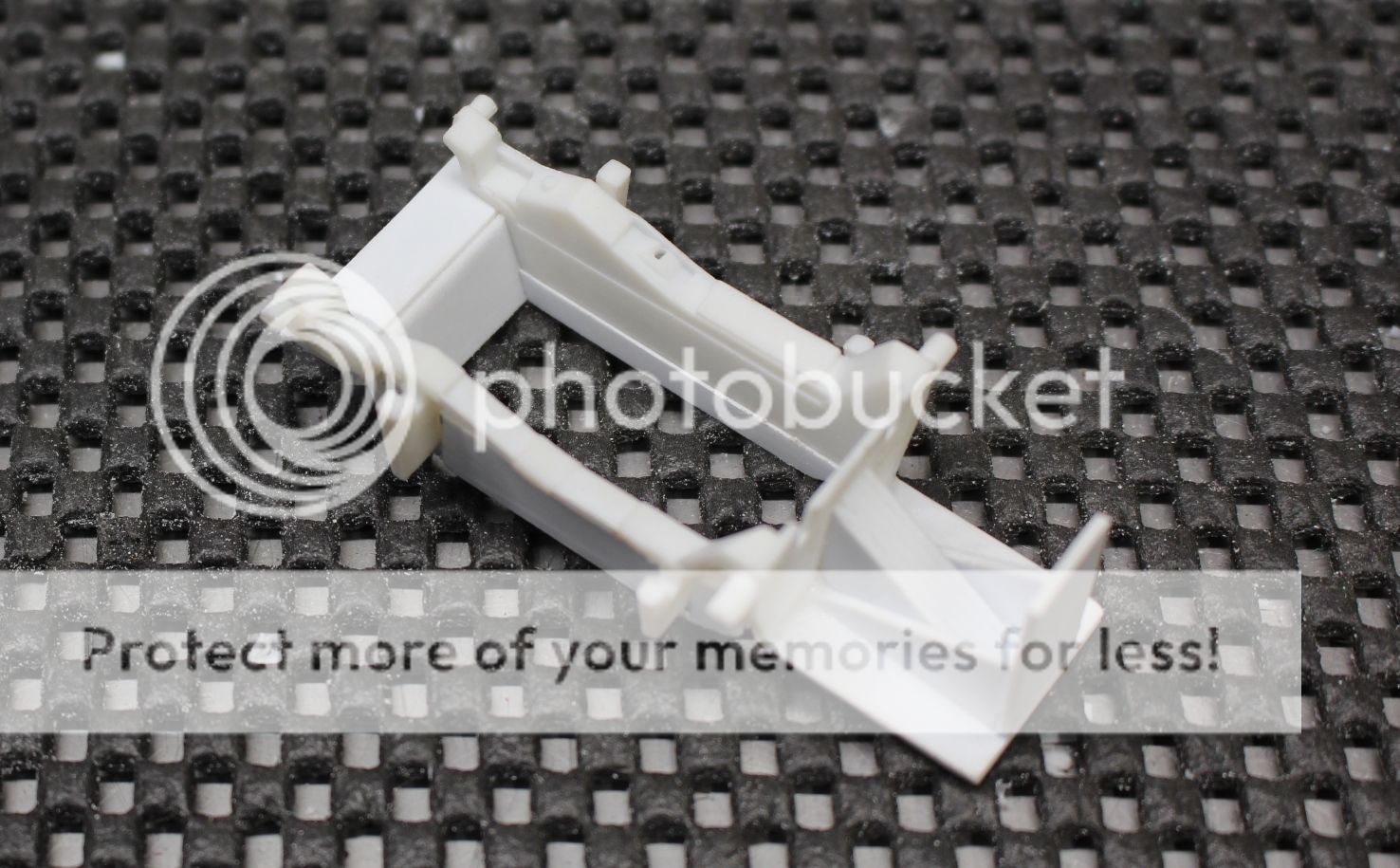
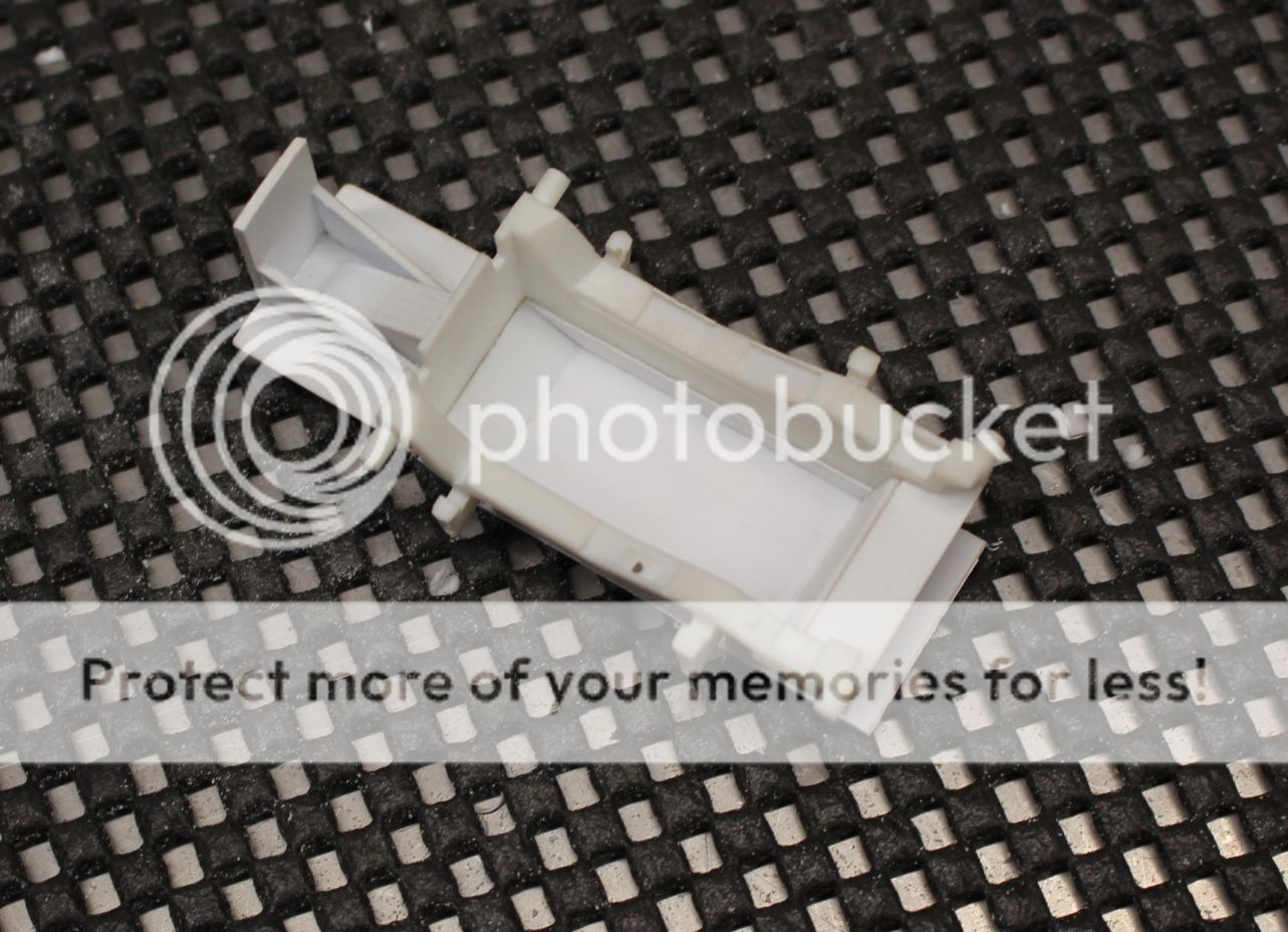
With the forward and rear bulkheads in place it was time to add in the sides. These (like the rear bulkhead) were pushed outward beyond the gear door opening to be able to house the gear door retraction mechanisms that'll be made later on:
And here is the gear well box with sides, sanded smooth on the outside and ready for a final test fit:
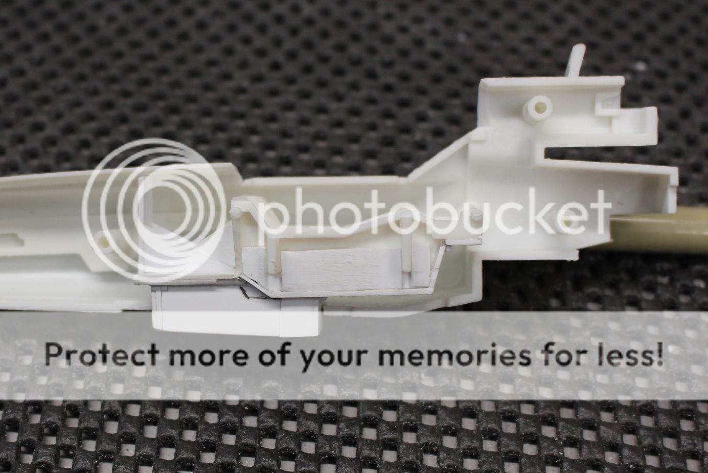
The box installed into the cockpit floor without p/n 9:
And finally with p/n 9 taped in place:
With the forward gear box complete, work will now turn towards the two main gear wells. I'll construct the gear wells first and once they are done my plan is then to add some of the other smaller details.
I'm still toying around with ideas on what to put in for details (if any) into the gear well in the nose. The cockpit tub was designed to break away to act as a survival pod if the pilot couldn't eject, which will play into the design. The question really is whether the nose gear (as it was part of the cockpit floor) would break away with it, or remain with the forward (discarded) nose section.... I guess I'll just have to watch a few more episodes with Viper battles to see... oooooh nooooo....
More soon!
Cheers,
Mark. -
This is such a cool project! The interior looks just so... spot on! I can hear Marty and the Doc in the background as I look at the build.
1/32 Viper Mk.II (Revell/Moebius + Extras)
in Sci-Fi Modeling
Posted
Si,
First off, your build is something else (speaking to the Star Destroyer). Working with small pieces of plasticard here is one thing... what' you're doing is a whole new level of added details. As for what you wrote about the aversion of replicating props and this build peeking your interests, well, thank you kindly! I really do appreciate your comments.
Work on the seat back, because, you know, the seat is taking FOREVER to work on... rather than going right into the plastic building of this part, I figured it would be a bit fun to go at the whole process starting with the reference images and research. There are two really great pictures that capture the shape and layout of the seat back. So here are the pictures and what I gathered from them:
A - There is a noticeable shape to the seat back and the head rest that follows a curve. There is a slightly noticeable break between the two pieces. The curve starts quite pointed at the top of the actual seat itself and carries right up to the top. The construction will duplicate this and I'll build the main seat back first, then focus on the head-rest portion afterwards.
B - The three 'blocks' often depicted and painted yellow and black (the middle one) are actually padded head-rest pieces that have a curve to them. This will be replicated using plasticard and I'll need to incorporate the curve into them, likely with a larger diameter or curved file.
C - The top portion above the head rests to protect the oxygen lines has two different thicknesses to them while the outside (thinner) pieces appear to be plates that go down the side of the head-rest. I'll make the forward piece out of 0.5 mm x 1.5 mm strips and the side pieces appear to be plates will be added as separate pieces afterwards out of 0.2 mm plasticard sanded to shape.
D - There are two long and thin plates that look like they'd be used to lift the seat on a hoist. The base of them has a bit of leg that bridges between the seat back and the head rest. This will be made using 0.2 mm with two small holes drilled in. To make it easy I'll use thinner strips to add the legs.
E - The shoulder harnesses appear to be fixed to the top of the back side of the seat back. It doesn't make sense for them to be fixed to the rear cockpit wall as that would be really bad for the health of the pilot ejecting... After this is all assembled and prior to installation, the two shoulder harnesses need to be pinned to the back and done right as they'll be visible.
F - These two lines (oxygen lines) have a small brass connector at the base. I'm going to have to muddle around to figure out exactly what diameter of wire will work and I'll use some Tamiya tape wrapped at the base and then painted brass to simulate this connector.
Here is the second picture which really helps with determining shape as the first image makes it look like everything is flat. Not the case:
Looking at the pads they have a bit of an inward, concave shape below the pads on the head rest where they meet up with the seat back. The sides have a curved shape to them that shows the side plates mentioned above in "C" that will need to be added. The outside of the pads though are quite flush with the head-rest. That defining line in "A" from the photo above is not recessed but rather it appears to be a groove between the head rest and the seat back. I'm also looking at the height here and the 1.5 mm plasticard strip will need a bit added to it (as I don't have 2.0 mm wide strips). The oxygen lines here have a bit of a flattened curve to them. As well, the bottom of the head-rest where it meets the seat back curves inward and slightly below where the shoulders of the actual seat are. This will be good to know when joining the seat to the seat back. From that point to the top of the seat back there is an inward taper to the shape. The forward face of the head-rest is rectangular, so there will be some creative sanding to get that shape.
Okay! So, now that there's a plan forward, it's time to fabricate these pieces.
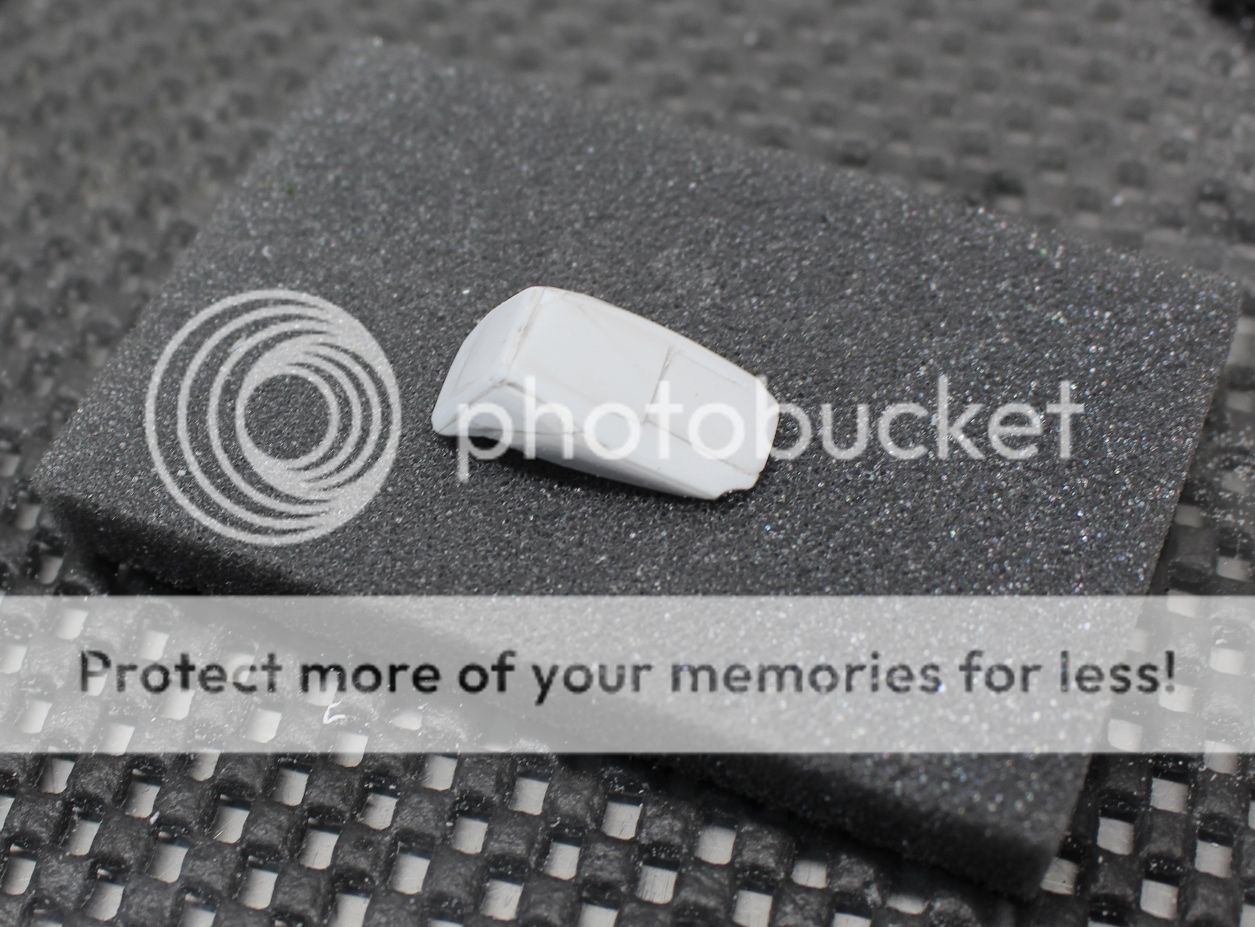
Much like the seat, plasticard was layered and glued together to get a good shape, then filed and sanded to get the seat back shape:
And here is the rough shape in the cockpit tub to make sure I've got the right height. It's all via the eye-ball sizing things up, and it looks about right here:
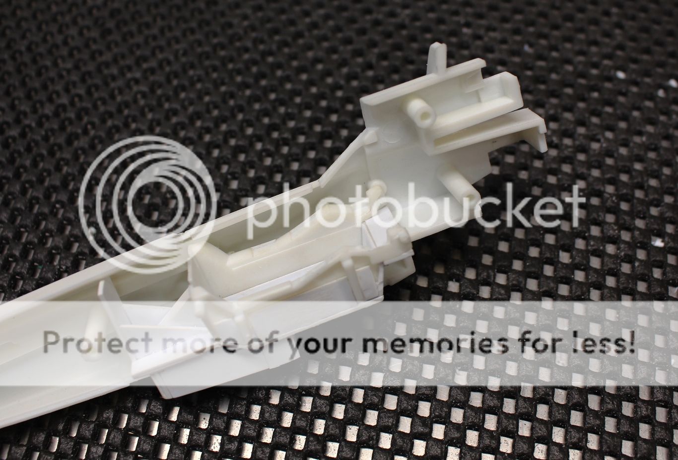
With the right shape to the seat back obtained it was time to build up the head-rest. Here are the thin pieces of 0.2 mm plasticard layered and glued down:
The head-rest was thencut down to shape with a hobby-saw, filed down and sanded:
Using files and sandpaper the head-rest was then given the rounded shape, and the plasticard strips were added for the head-rest pads. Once cured they were roughly sanded to shape:
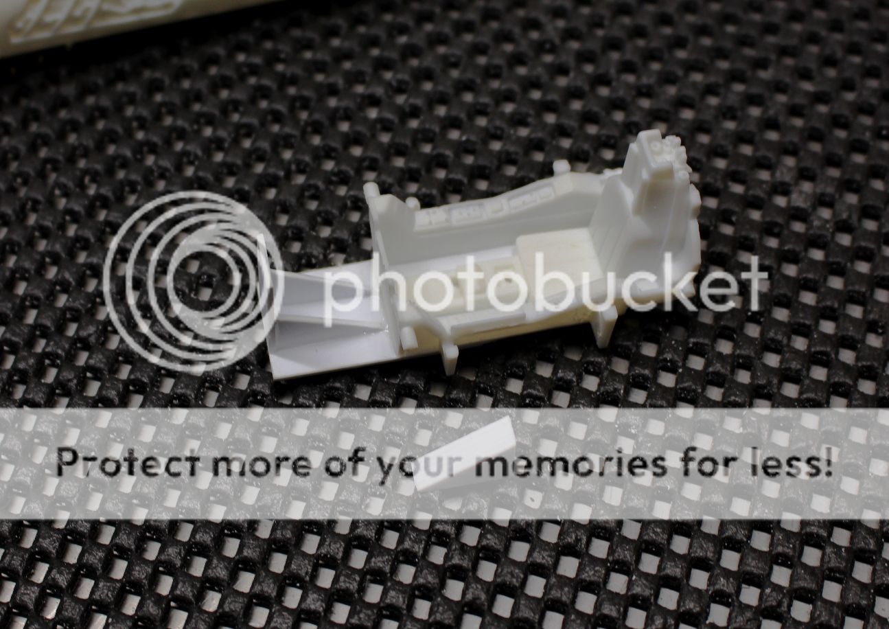
The construction of the top piece of the head-rest was started with that forward facing upper bar, and the two 'nubs' that the oxygen hose plugs into. Lastly, a thin piece of 0.2 mm plasticard was glued up along the sides of the seat back to add that 'grove' between the seat back and head rest:
From there the side of the head rest was sanded back even further to give that curved shape under the two side plates. The side plates were then cut out and shaped from 0.2 mm plasticard, then sanded down further to be a bit thinner. They were glued in place and allowed to cure:
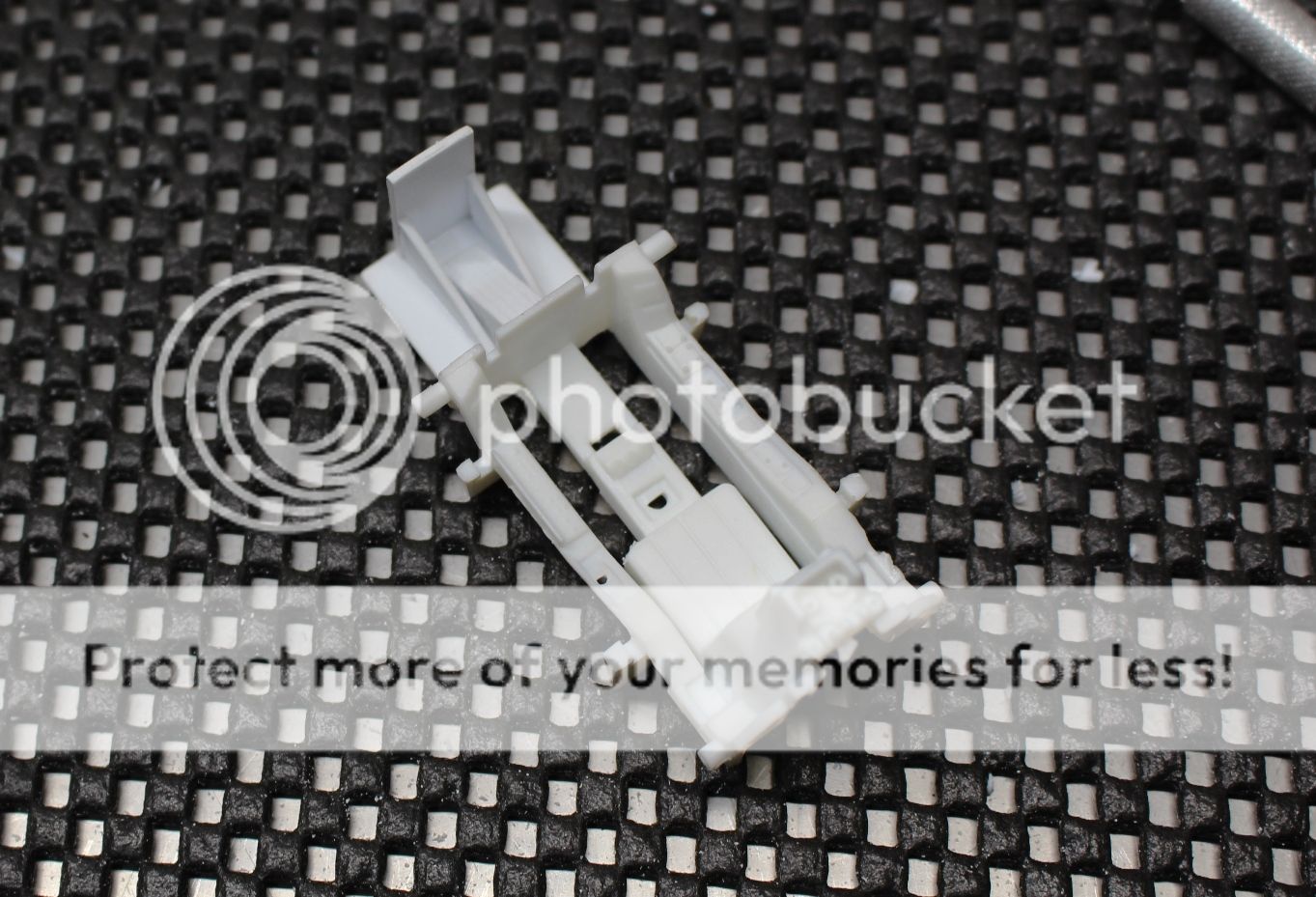
Last but not least on the plastic construction, the two thin posts and legs were added. From there the holes were drilled for the oxygen lines:
The piece was cleaned up to get rid of any extra plastic burrs, and smooth it all out with 800 grit sandpaper. Once cleaned, the seat back was sprayed with flat black and allowed to dry:
The piece was then given a few treatments of black and 80% grey pastel chalk to give the shape of this piece some definition and a bit of a warn look. No paint chips, just faded paint:
When it came to the two oxygen hoses I messed around a bit and found that the best combination was to have a core of 28 gauge milticraft wire, with 34 gauge tightly wrapped around in a spiral. Realistically this is just some conduit from the looks of it, but once the two wires were finished, they were cut to length, shaped based on the pictures as best I could, and glued into place:
A thin 1.0 mm strip of Tamiya tape was cut, wrapped and glued into place:
They were then painted bronze once the glue dried:
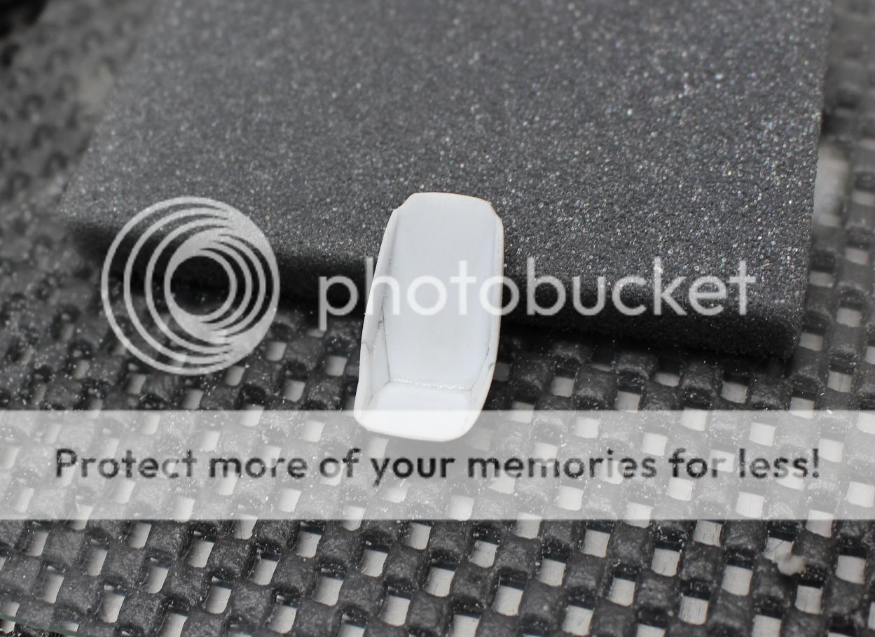
And here is the seat back sitting in the cockpit tub to size it up:
The next step will be to finally finish off the seat and attach the two pieces. Once that's done the final details can be added.
Thanks for looking,
Cheers!
Mark.