

Witold Jaworski
-
Content Count
176 -
Joined
-
Last visited
Content Type
Profiles
Forums
Calendar
Everything posted by Witold Jaworski
-
 I am working on the new (fourth) edition of my "Virtual Airplane" guide. Last week I completed its second volume: "Modeling". It describes, how to build an accurate 3D model of a historical aircraft, on the example of the Curtiss P-40B fighter. Comparing to the previous edition (from 2015), I rewrote 80% of its content, introducing significant changes in the proposed workflow (taking advantage of the new Blender features, which have been introduced since that time). In 2020 I already published the first volume of this series: "Preparations". This means, that at this moment we already
 -
P-40B (based on the original Curtiss blueprints)
Witold Jaworski replied to Witold Jaworski's topic in In-Progress Pics
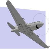
In this post I will complete the 3D reference that I started in the previous post. Here is a link to the Blender file that contains 3D reference skeleton of the "long nose" P-40, described in the text below. It was compiled from all available blueprints. Studying the dimmed blueprint scans, I was not able to read some horizontal ordinates placed close to the top and bottom segments of this fuselage. This created gaps in my 3D grid (Figure "a", below): Fortunately, in the fuselage ordinates diagram (dwg 75-21-020) I was able to identify ordinates of two vert -
P-40B (based on the original Curtiss blueprints)
Witold Jaworski replied to Witold Jaworski's topic in In-Progress Pics
Thank you for reading! 🙂 -
P-40B (based on the original Curtiss blueprints)
Witold Jaworski replied to Witold Jaworski's topic in In-Progress Pics
At this moment I am working on second volume of my book about 3D modeling. It describes building a 3D model of a WW2 aircraft on the example of the P-40B. Preparing for this work, I discovered that the original documentation of this early P-40 variant (also known as "long nose Warhawks") is missing. On the other hand – you can find plenty of the "short nose Warhawk" blueprints (related to the P-40D later variants), as well as some P-36 drawings. I started by picking over 1000 original Curtiss blueprints and sketches related to the P-40, XP-40, and the P-36 from the vast resources of the AirCor -
I decided to upload the Blender file in which I reproduced in the 3D space the original ordinates of the SBD fuselage and wing. (I described creation of this 3D reference in my previous posts). I think that in this form they can be useful for other modelers, who would like to recreate the geometry of this aircraft. Here is the link to the *.blend file (102MB) that contains the model presented below: The fuselage ordinates are organized into horizontal “water lines” (blue), vertical “buttock lines” (green) and resulting se
-
P-40B (based on the original Curtiss blueprints)
Witold Jaworski replied to Witold Jaworski's topic in In-Progress Pics
A new source of the accurate aircraft geometry and original blueprints! (this is an update of post #1 from this thread, because the blueprint source I recommended there - the plans.aero portal - disappeared a year ago) For over ten years Hugh Thomson has published marvelous posts in his blog about the historical aircraft. Just look there to see the P-51 Mustang, F6F Hellcat, F4F Wildcat and B-25 Mitchell CAD models and – what is sometimes even more important – compiled datasheets of their ordinates. The true, accurate geometrical data are usually dispersed and dif -
P-40B (based on the original Curtiss blueprints)
Witold Jaworski replied to Witold Jaworski's topic in In-Progress Pics
Thank you! However in this case you can see the effect of their skills with this CNC machine, not mine 🙂 -
P-40B (based on the original Curtiss blueprints)
Witold Jaworski replied to Witold Jaworski's topic in In-Progress Pics
A little bit off-topic: An interesting project realized by BEK Milling Solutions. Their CNC machine is cutting out a P-40 model in 1:2 scale, from a styrofoam block. For the input geometry, they used my old model of the P-40B: Actually, I am working on a more accurate one, based on the original blueprints. However, their deadlines did not allow them to wait for this update. -
P-40B (based on the original Curtiss blueprints)
Witold Jaworski replied to Witold Jaworski's topic in In-Progress Pics
Yes, I suppose that modeling various cast details, like engine crankcases, hydraulic hubs, etc. is much easier in such a full-blown CAD/CAM like Fusion 360. The main reason is its advanced functionality for modeling various fillets. Blender lacks it (its bevels/fillets are restricted by the edges of the two adjacent faces), which makes modeling such complex shapes quite difficult. This is the advantage of this Autodesk product. However, for my ultimate goal (creating aircraft visualizations) Fusion 360 also has some drawbacks: the lack of advanced, physics-based render en -
This February I found among the SDASM resources a diagram (dwg no 5060837), which describes the geometry of the SBD fuselage. This is the key piece of the information that was missing in the NASM microfilms I used before. Below you can see these lines: The original drawing is slightly distorted. I was able to stretch its upper and lower portions, so in the central part its rectangular “grid” fits the blue guide lines drawn in Inkscape. However, this is a non-linear deformation, so it still occurs along the edges of this image. (In the illustration above, I marked the
-
This time a technical post about the overall dimensions of the subsequent Dauntless versions. We are using these values for scaling the reference drawings. If they are wrong - the whole model you are building is also wrong. That’s why they are so important: _________________________________________________________________________________________________ Since 2015 I have tried to determine the true length of the early SBD Dauntless versions (the SBD-1, -2, and -3). There was something wrong with the source of this information: the original BuAer performance data sheets. You can find the
-
I just published a book which discusses details of preparing/using reference drawings. I think that it can be useful for all modelers, including "plastic kit" modelers and the authors of the scale plans. Among other issues, it includes some materials presented in this blog. See here for details.
-
P-40B (based on the original Curtiss blueprints)
Witold Jaworski replied to Witold Jaworski's topic in In-Progress Pics
This June I started working on a new (fourth) edition of my book about aircraft computer models. Actually, I am finishing its first volume (“Preparations”). It describes how to prepare accurate reference drawings of a historical airplane, on the example of the P-40. Below you can see two of its pages (as they appear my screen): Comparing to the third edition, I altered here the proposed workflow, using Inkscape as my basic tool. I also wrote more about eventual errors, which you can find in typical scale plans. In the appendices I included a section about the original P-40 blueprint -
(Continuation of the previous post) After shaping this side contour (it corresponds to longeron #01 in the SBD skeleton) I also recreated the 14 remaining longerons. Their locations match the structure of the real aircraft: In fact, it was quite slow process: I had to fix minor differences in the bulkhead shapes along each longeron. Sometimes the line of newly added longeron forced me to correct the previous one. The surfaces of front and rear wing fillet cones were a great help: without them I could not properly form the complex shape of longeron #09 or longeron #12.
-
(Continuation of the previous post) The updated, somewhat shorter outer wing segment fits much better the reference photos (this is another confirmation that I read properly its assembly drawings). Now I used these photos for checking the fuselage side contour: It is interesting that in this way I am comparing the real aircraft with its blueprint (in this case – the side view of the structure assembly). As you can see in the picture above, I found some differences along the upper edge of the tail. Figure below shows their details: First,
-
In previous post I started creating 3D reference objects for the SBD fuselage. In this post I will complete this work. I will focus here on the difficult part: the wing fillet. It spanned along more than half of the SBD fuselage length. In this post I am going to prepare reference geometry that describe its shape from bulkhead #4 to bulkhead #13. Unfortunately, in drawings from the NASM microfilms I found just a few contours related to this feature: Figure "a" above shows horizontal contour of this fillet, which I found in the panels assembly diagram (dwg 5063493 –
-
The current version, i.e. Blender 2.8, but most of my posts (and the book) describe Blender 2.7
-
(Continuation of the previous post) That was the easier part. Now I have to recreate the tail bulkheads. As you can see in the first illustration in this post, I found only the upper parts of frames #13..#16, and complete closing frame (#17). They contain just a few usable dimensions. Paraphrasing well-known Goya’s title, “the lack of dimensions produces assumptions”, and assumptions are the main source of eventual errors. However, there is no other way. In this case I have to make several assumptions about the shape of tail bulkheads. Of course, first I reviewed all the blueprints f
-
As I already mentioned in this post, my microfilm set does not contain the fuselage geometry diagram. (I suppose that it was included in the missing roll C). Thus, this part of my work will be much more difficult, because I even do not have complete set of the bulkhead drawings! Just found a structure assembly drawing (i.e. side and vertical views), skin panels assembly drawing, mid-fuselage bulkheads, and some bulkheads of the tail. In the picture below I marked these undocumented areas of the fuselage in transparent red: Douglas blueprints refer to the fuselage bulkheads as “frame
-
In some aircraft it is difficult to provide the precise value of overall length. One of them is the SBD Dauntless, because of its easily demountable spinner used in the first three variants (SBD-1…-3). Also the length of the Hamilton Standard Hydromatic spinner hub, used in the later SBD variants, can vary – especially in the restored aircraft. Thus, for verification of model kits or similar purposes I would suggest checking the distance between two easily distinguishable points: from the firewall to the tip of the tail cone. This dimension remains the same in all SBD variants. Preparing the f
-
salomon, these visualizations are superb! They look like real photos! (All these blurs around engine nozzles, and so on...) What modeler/render engine do you use. Did you make some of these final effect in the postprocessing phase?
-
In this posts I will analyze differences between my 3D model (built from 2015 to 2019, as reported in this thread) and the SBD geometry data obtained from the original documentation. Actually, I can perform such a ultimate comparison for the wing, because I found its original geometry diagram in the NASM microfilm. In previous post I used it for preparing a “reference frame” for such a verification. Results of this comparison will allow me to determine the real error range of my previous methods described in this blog, in particular – the photo-matching method.
-
(continuation of the previous post) I placed on this drawing the free-form curve key points, following the explicit dimensions specified in the master diagram, and connected them with a curve. I was surprised, discovering that the central part of this contour does not fit both drawings: The difference between these contours is quite significant and reaches about 0.4” near the auxiliary reference plane. All what I could do in such a case was checking this detail in the available photos (especially the archival photos). Unfortunately, it is impossible to precisely compare this sh
-
(continuation of the previous post) I also made another error. Building the wing model I assumed that declared, 15% thick airfoil NACA2415 at station 66 (joint of the center and outboard wing section) was perpendicular to the reference plane of the outboard wing (i.e. to the wing airfoils chords plane – see figure above). In the effect, I obtained the oblique rib (10.2°), adjacent to the wing center section, as 15.24% thick. Now from the STA 66 ordinals of I learned that they used the 15% NACA2415 for the oblique rib, thus the real wing was somewhat thinner than in my model. I
-
I am preparing data from the original Douglas blueprints to verify my model. For the beginning I chosen the wing. This is a well-documented assembly, because I found a master diagram in the NASM microfilm that describes SBD wing geometry (ordinals). Below you can see the first sheet of this diagram (dwg no 5090185): Here you can download its high-resolution version (5MB). As you can see, it contains the ordinal tables of the wing bulkheads (ribs) and webs (spars). In the sketch on its right side Douglas engineers depicted various other dimensions of the wing center section. In the p