


Timmy!
-
Content Count
553 -
Joined
-
Last visited
Content Type
Profiles
Forums
Calendar
Posts posted by Timmy!
-
-
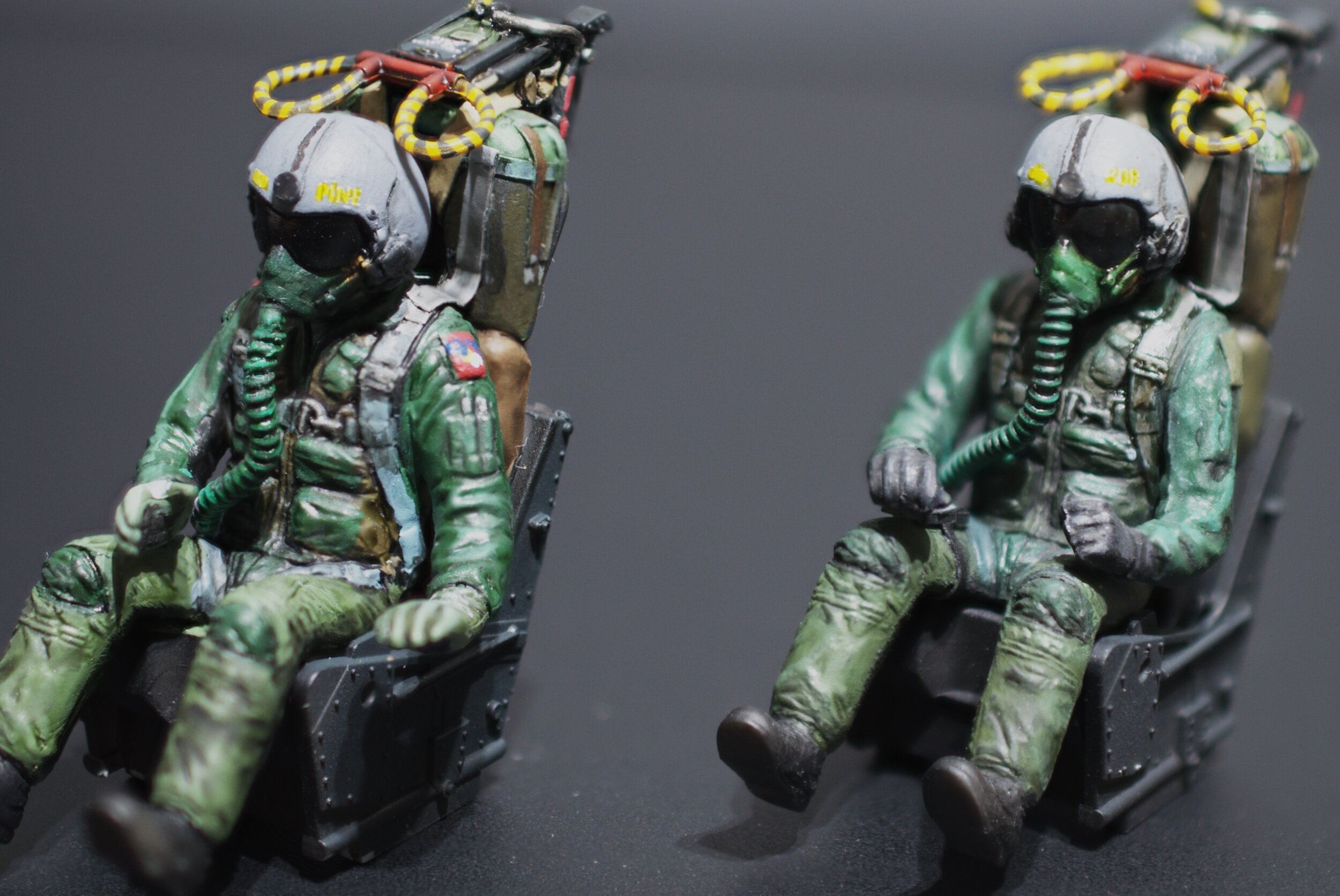
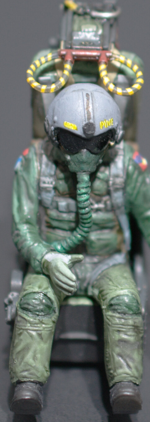
Hey guys I’ve got a side gig going. I’m going to knock out a Tamiya 1/32nd F-4EJ改 KAI. This will be another inflight model. Mounted on a runway base, where I’ll do that cool motion blurred effect. Also I’ll be adding some electronics, lights sound and app controlled over Blue Tooth.
Pilots are complete. Oh and by the way this will be a video series.
Hope you like what you see!
Here’s my vid…
The cockpit is next…
Thanks for tuning in!
Timmy!
-
17 hours ago, Trojan Thunder said:
Timmy, I have posted your request over on the Aussie Modeller Forum
Great! hopefully that will turn up some leads.
-
‘Allo Bruce!
I have a very good friend in Sydney who has a few kits he would like built. A Vampire, a Lysander and one other I believe. The Vampire will require custom markings as it will need to represent a specific airframe. If you have interest, skills and time to build up a few kits, please pm me and I’ll introduce you to the client and you two can make a deal that’s fair dinkum.
Cheers,
Timmy!
-
21 hours ago, crackerjazz said:
Gorgious paint job, Tim! Looks very realistic! What do you call that thing on the lower left side -- the one with the coiled cable? I see it on pics of other aircraft -- is it a hand-held microphone?
The technical name is a utility light, but also known as a grimes light. Not sure how it works on the Jag but in the planes and helicopters I flew, the light has a dimmer and beam adjustments and you could change color, white to red or white to blue on night vision goggle compatible cockpits. It’s basically a wired flashlight, it pops out holder and the pilot can use it to find stuff or read his kneeboard.
Timmy!
-
Hello all,
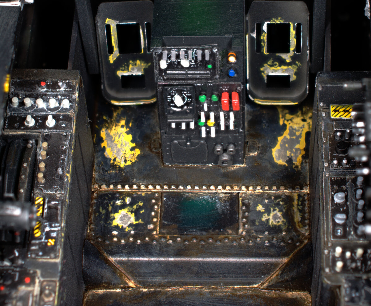
Got a good bit of the cockpit done.
Had a great time working on this. I’ll say this is the first time I’ve added dust and dirt to a model cockpit. Many photos of these jets show a good bit of dust and dirt and nothing ventured nothing gained so I went for it. Photos exaggerate the effect, mostly because with so much black paint lots of contrast is needed to see details.

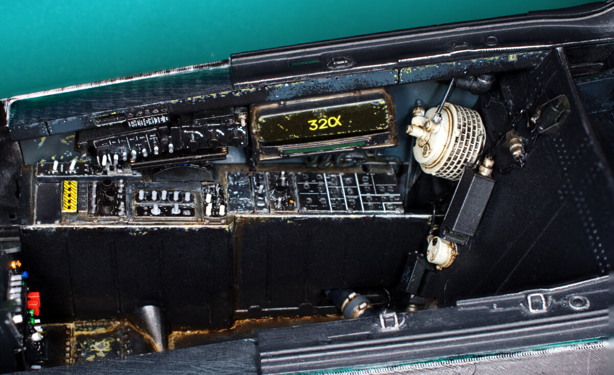
Hey what’s a tank doing here? Read the article….
Thanks for checking in guys…
Cheers,
Timmy!
-
2 hours ago, salomon said:
Just amazing, I love your build.
By the way I have a question; is there a lot of sanding work with this 3d printing process?
Thanks!There is quite a bit of work to do on the fdm prints, the resin prints no much to do except remove supports and light surface touch ups.
-
Thanks for the support guys...
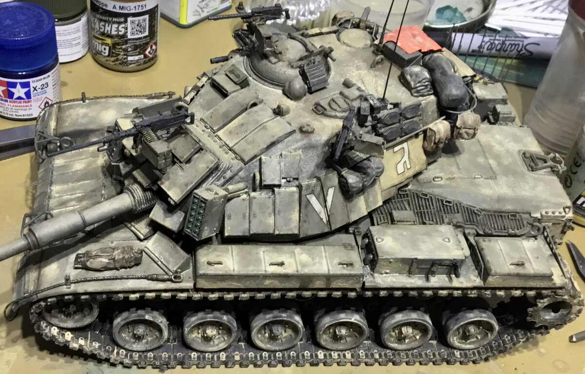
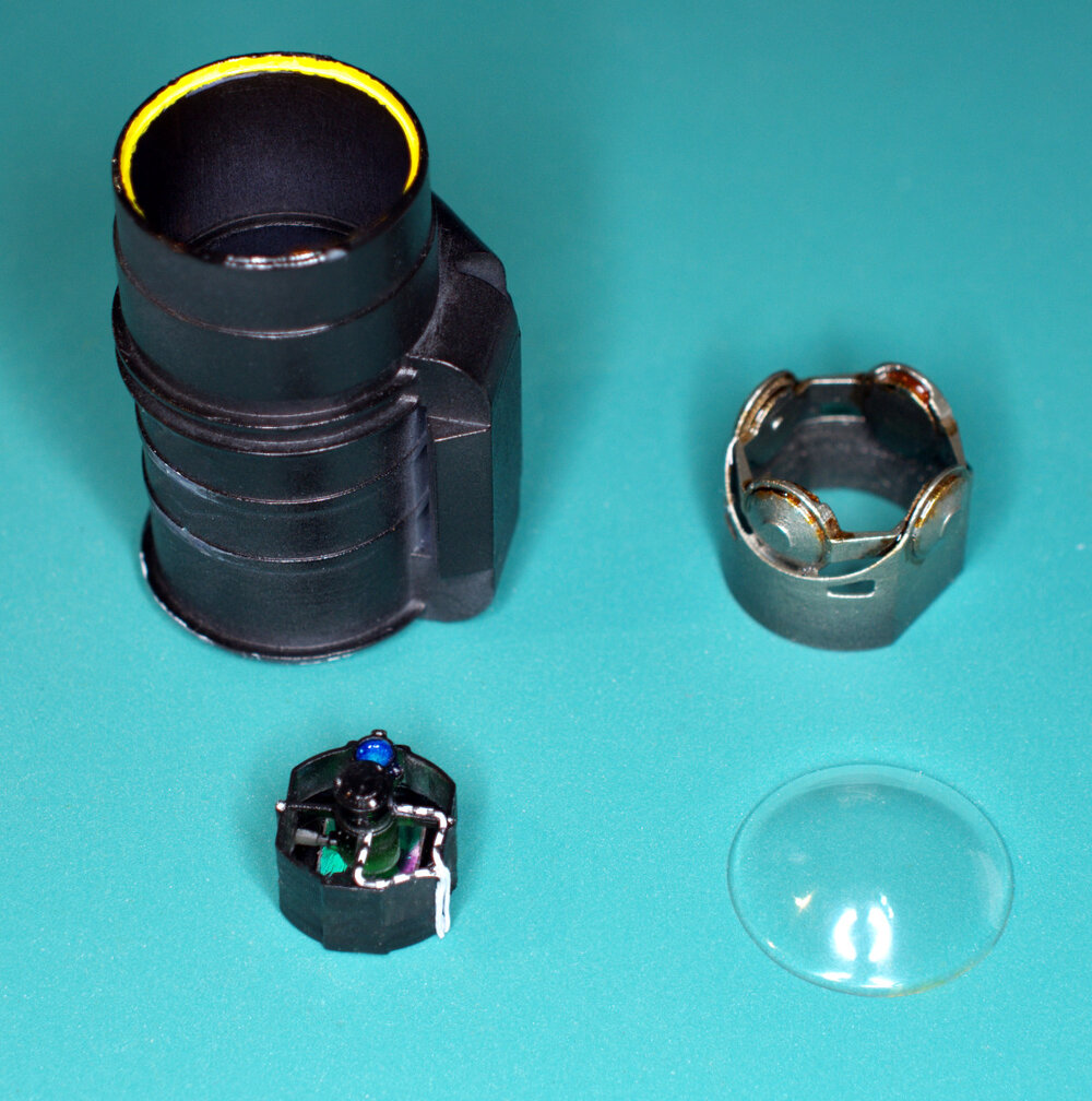
Hello Boyos!
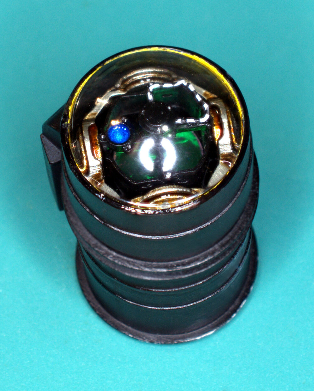
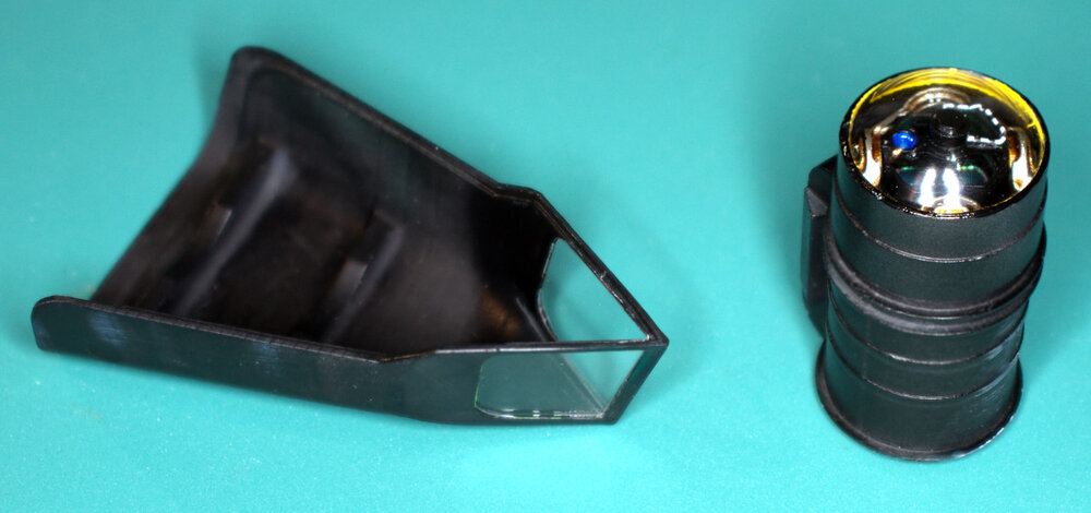
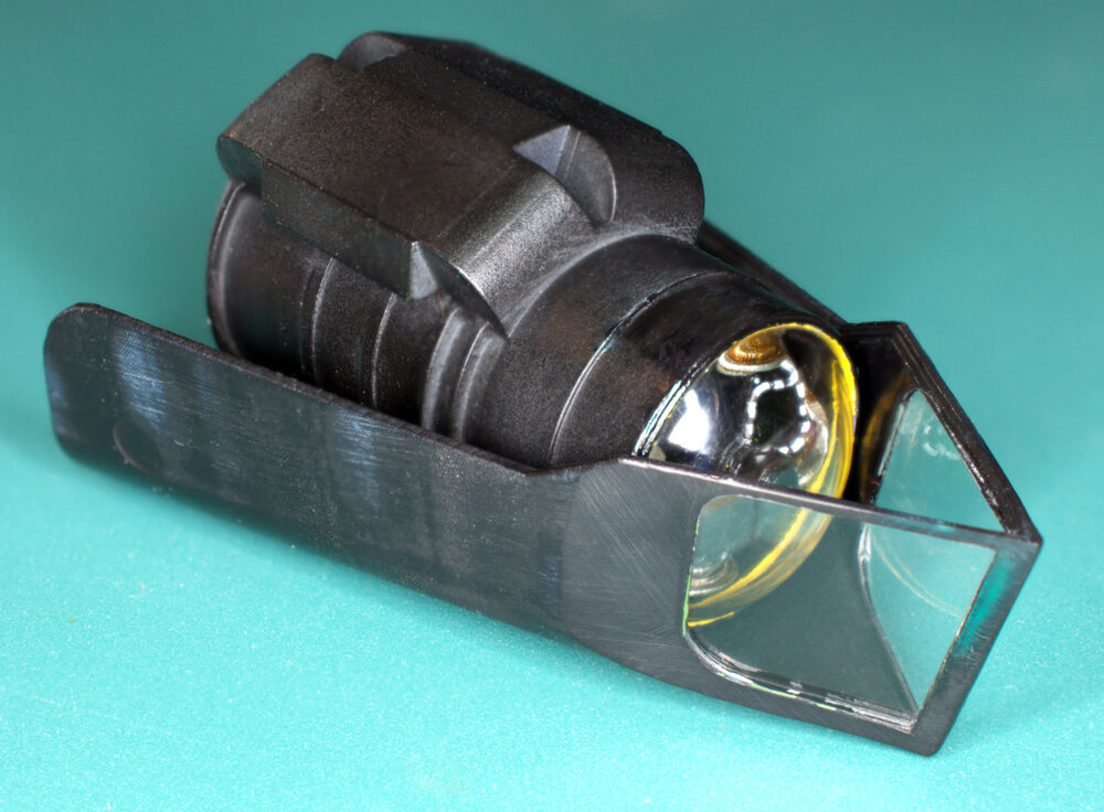
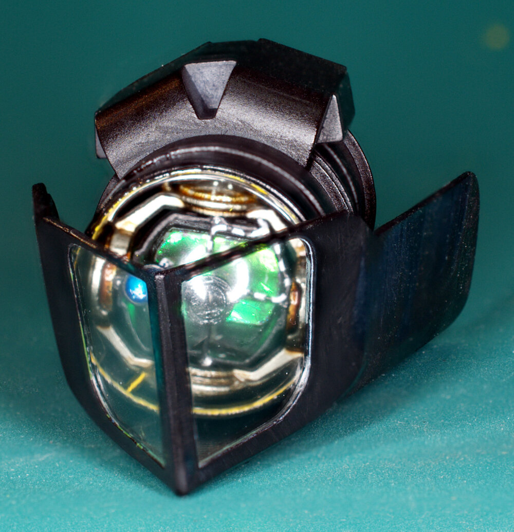
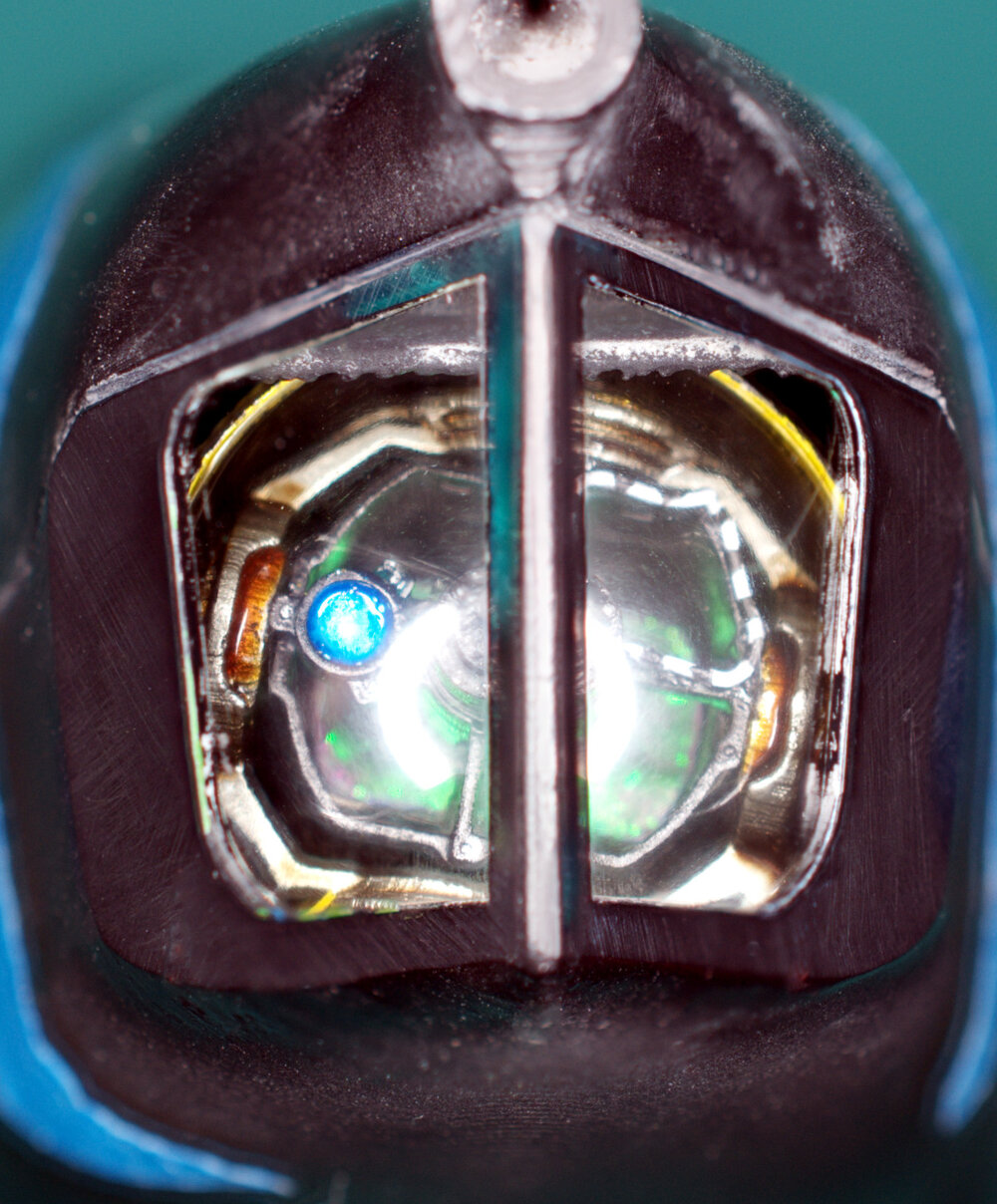
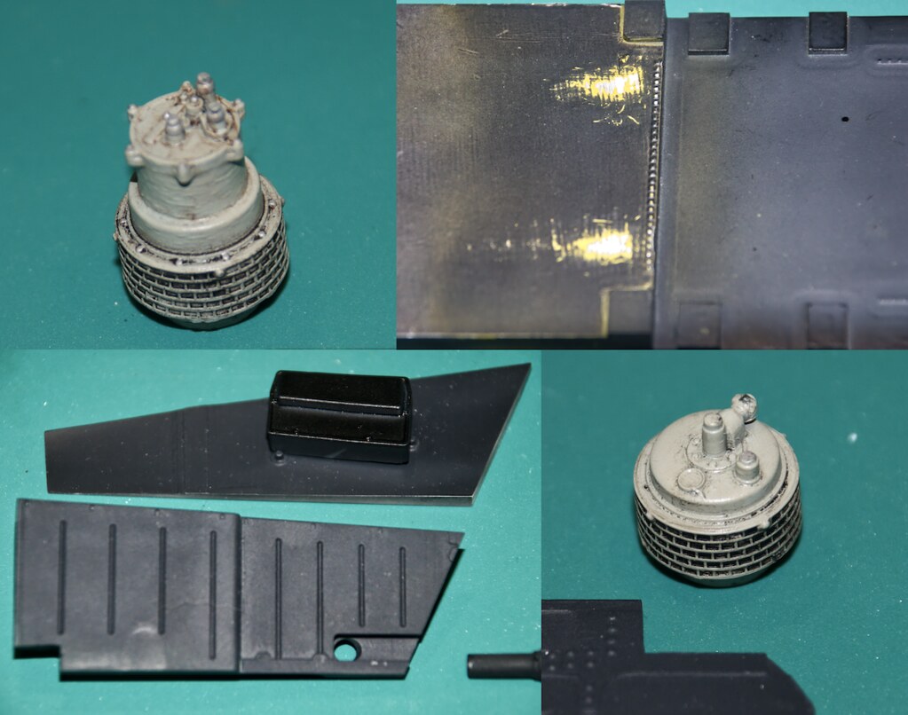
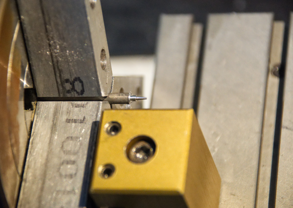
Quick update I finished up the LRMTS.
It’s a short article this time so head on over here for the complete write up.
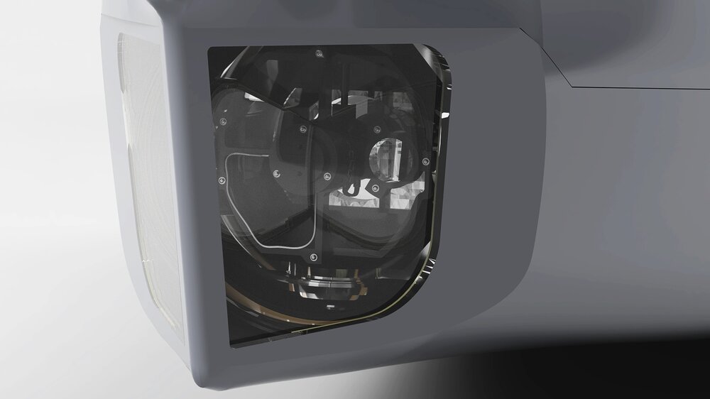
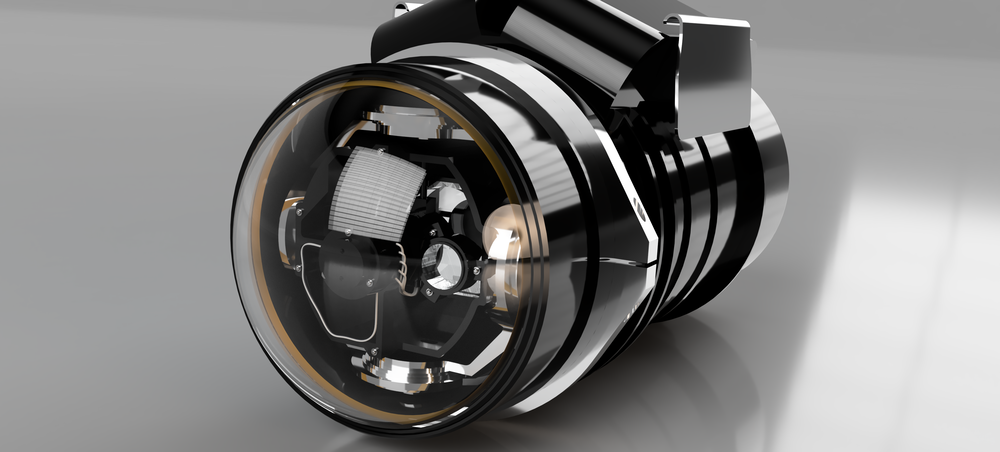
Of note the clear cover was milled vs. vacuum formed.
More soon thanks for stopping by!
Cheers,
Timmy!
-
Thanks everyone for checking in and the kind comment are as alway much appreciated.
Timmy,
This is incredible work. Just outstanding. Could you post a couple of pics with something we could use as a scale reference. I'm curious to see how small this detail is. Thanks and congrats on the amazing work so far!
I'll work on that...promise.
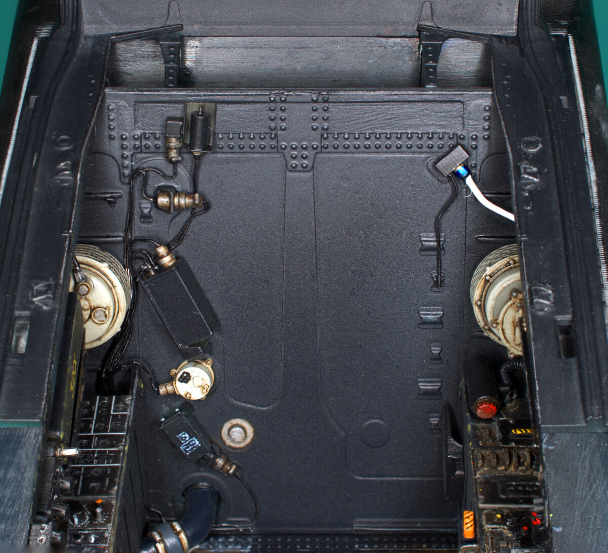
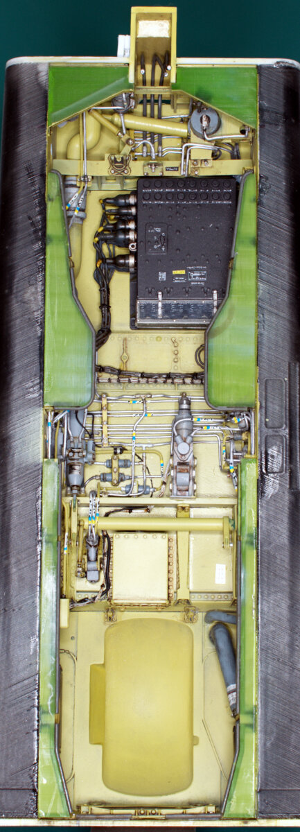
It’s DONE!! Well the nose gear well at least. It’s been more of the same work I’ve previously posted, just more of it. Getting the last bits of wiring and tubing installed at the halves and front and rear bulkhead came together was a bit of a challenge. The are a few lines that proved impossible to install. But none of the ones I couldn’t get to can be seen easily or at all. In fact there’s a good bit of detail that will be difficult to see when the gear and doors are installed. You never know what will be seen or not until everything is installed so I put the details in.
On to the photo’s:
The CAD model as it exists today, a good chunk of time was spent updating the model with new parts for printing.
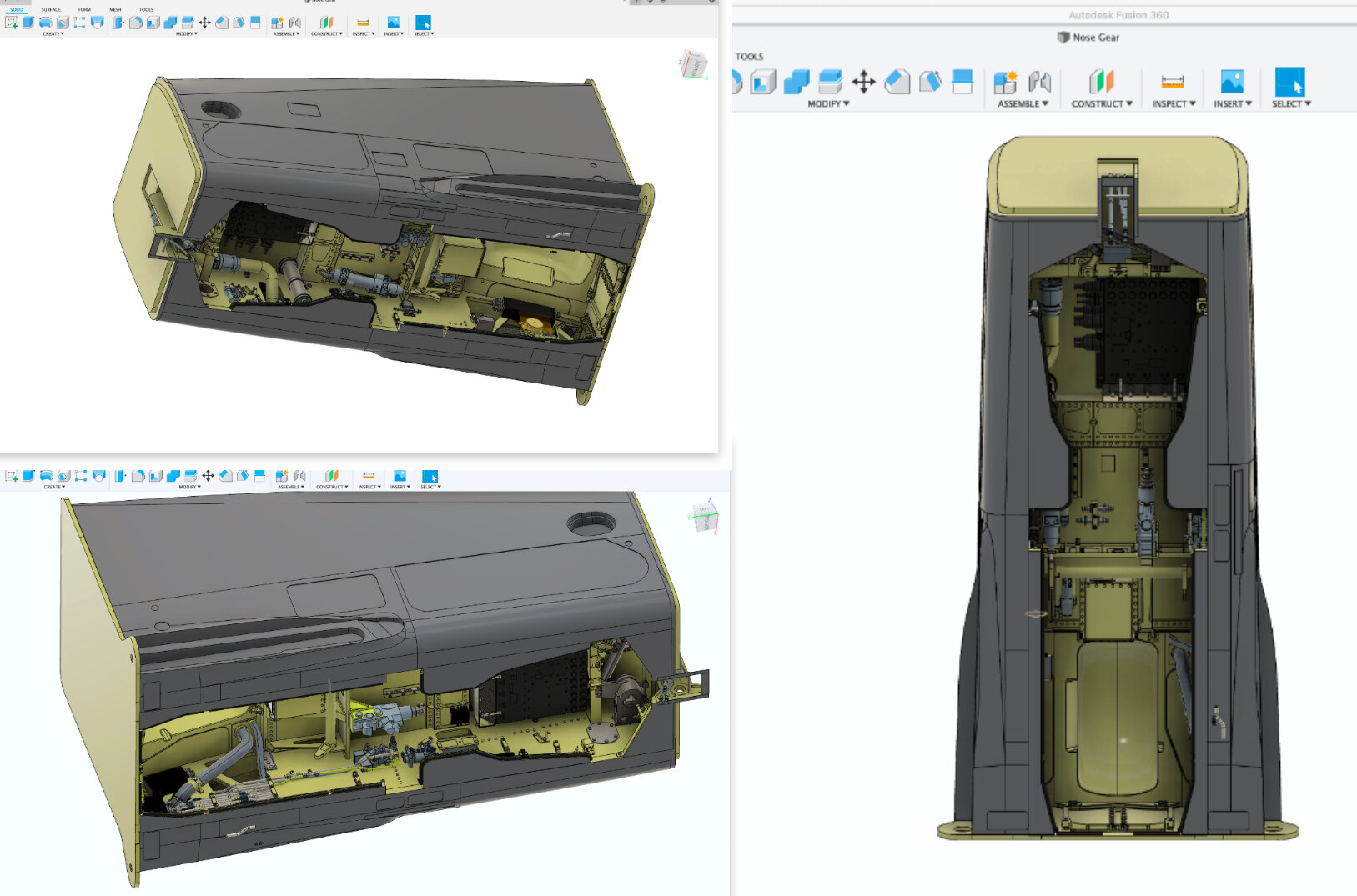
The completed well:

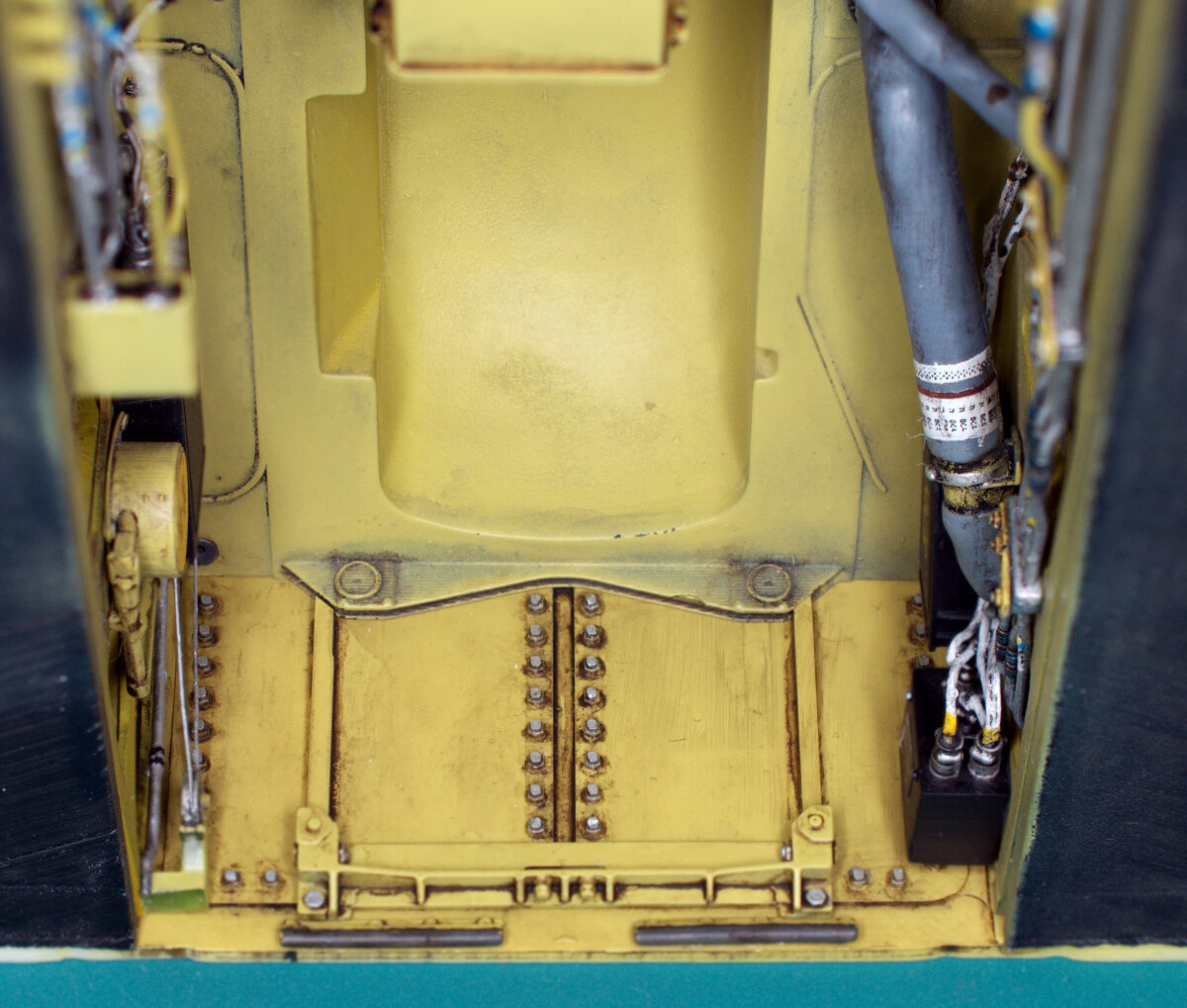
The last parts to install were the “filler” parts that close off the well and define the door opening.
That’s all for now…
Oh and I created a new template for my website, that I hope is a little more modern and user friendly. Feed back welcome.
Full article here.
Timmy!'s Tech Jaguar Nose Gear Well
Thanks, as always, for stoping by.
Timmy!
-
Quick update. More tubing and parts added. Getting close to closing up the nose gear and cockpit assembly. Lots of parts needed to be modeled up printed and attached. Plus no small amount of time figuring out where the plumbing goes. I'll do a complete write up of the nose gear well and publish a complete article on my website once the assembly is complete.

More soon....
Timmy!
More soon....
Timmy!
-
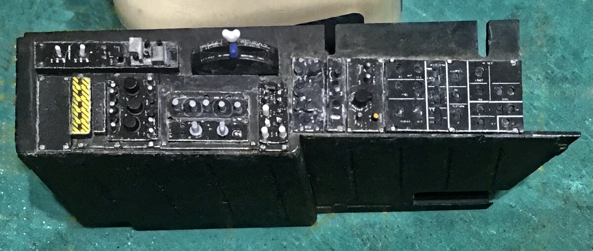
Time to take a little break from tubing!
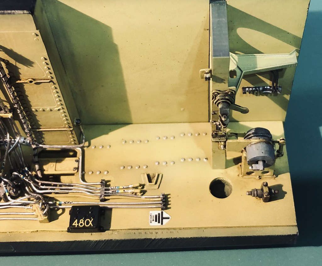
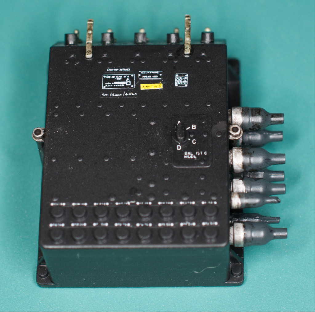
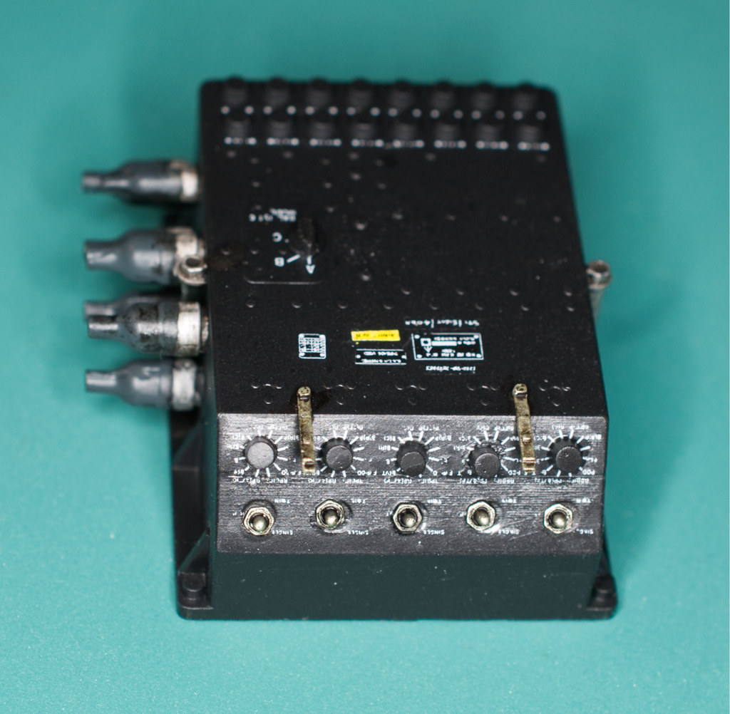
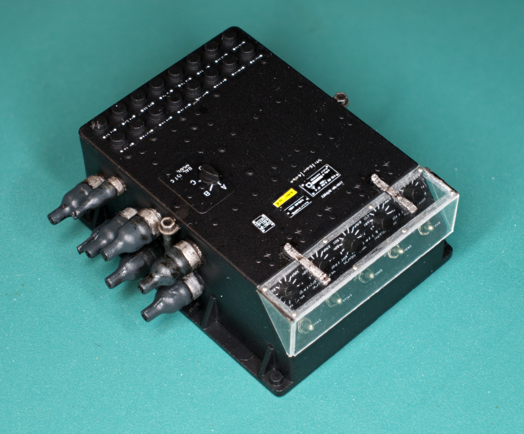
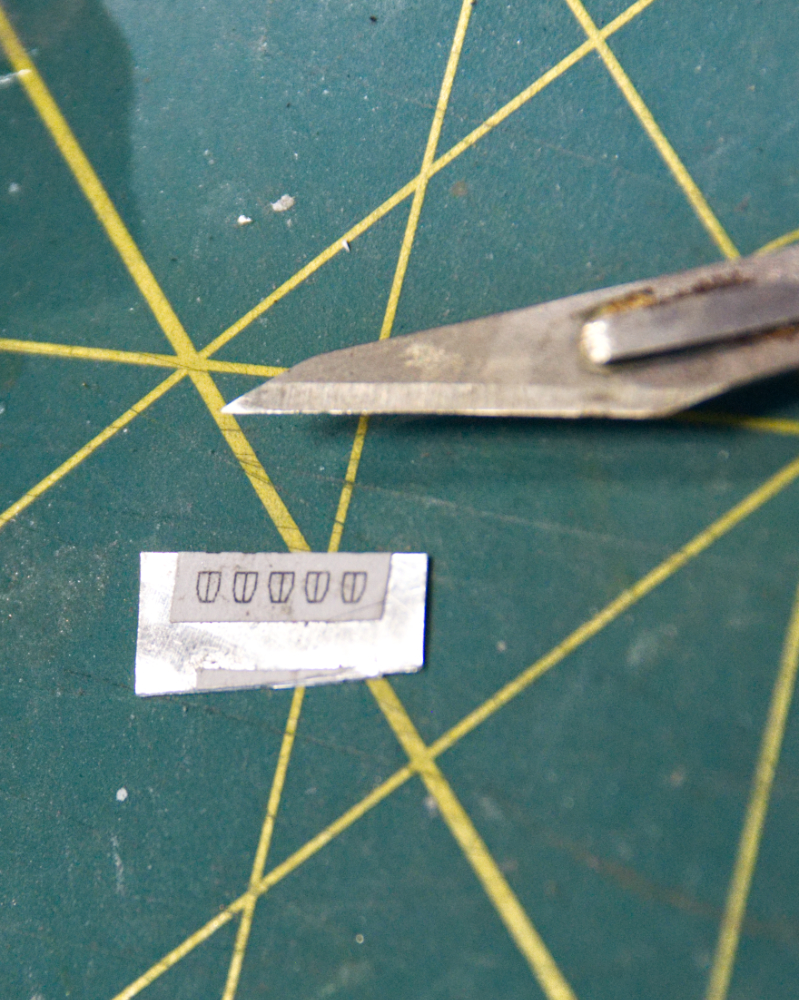
Here is the Weapon Main Unit, part of the control of the five stores hard points. It' s a good warm up for the cockpit detailing to come. The main box was printed along with a block of switches and knobs. The clear cover was cut from Evergreen clear 0.010" styrene and scored and folded to it final shape. The upper portion masked and sanded to create the frosted border. Fairly simple paint job, black body, aluminum wire connections, switches and cover latches and dark grey wiring boots. After a coat a Future decals were applied and a little thinned oil paint was used to pick out details and add some grime. Finally a coat 50/50 flat and gloss lacquer to unify the finish and the cover was attached.
Plumbing is about half done so that's next....

More soon and thanks for checking in!
Timmy!
-
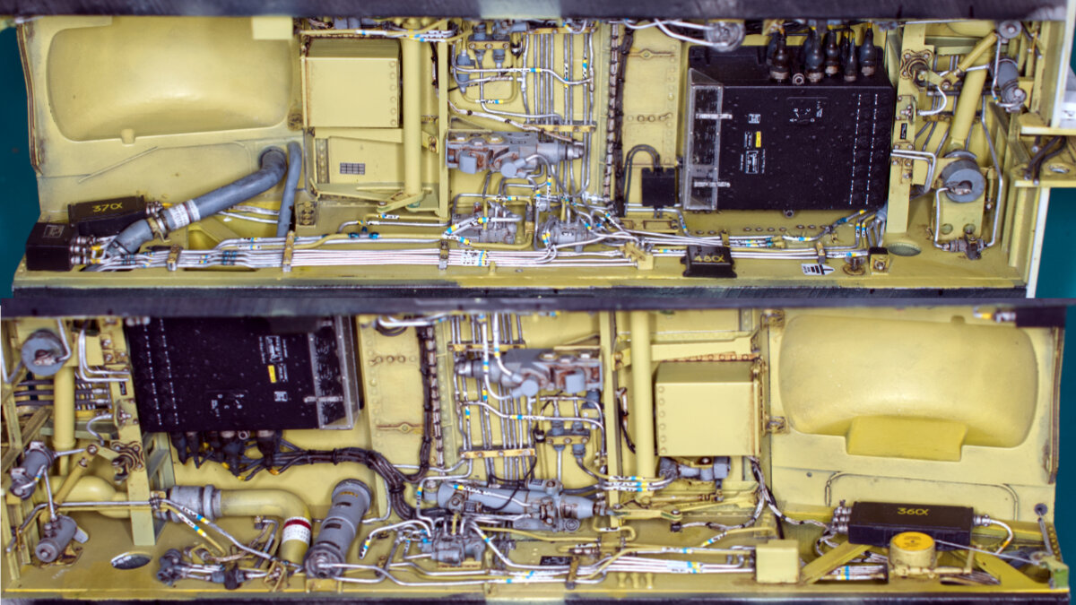
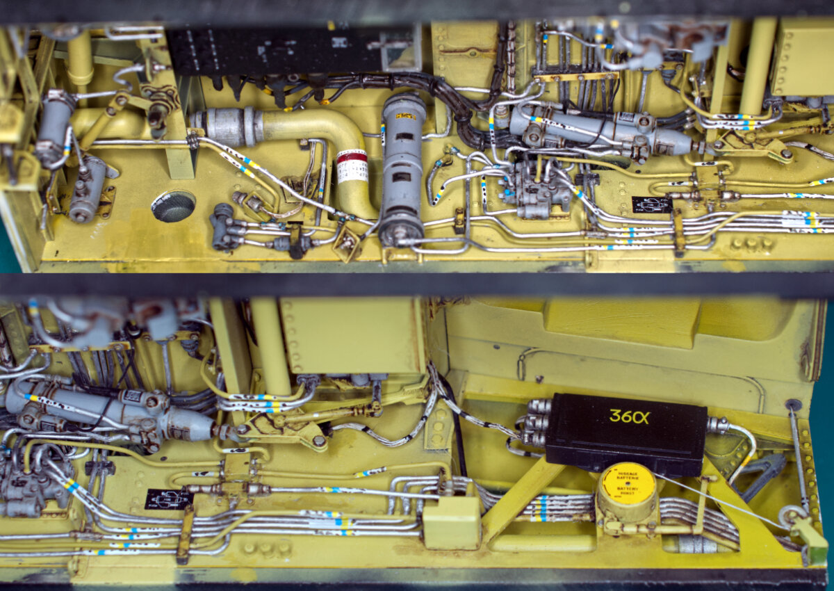
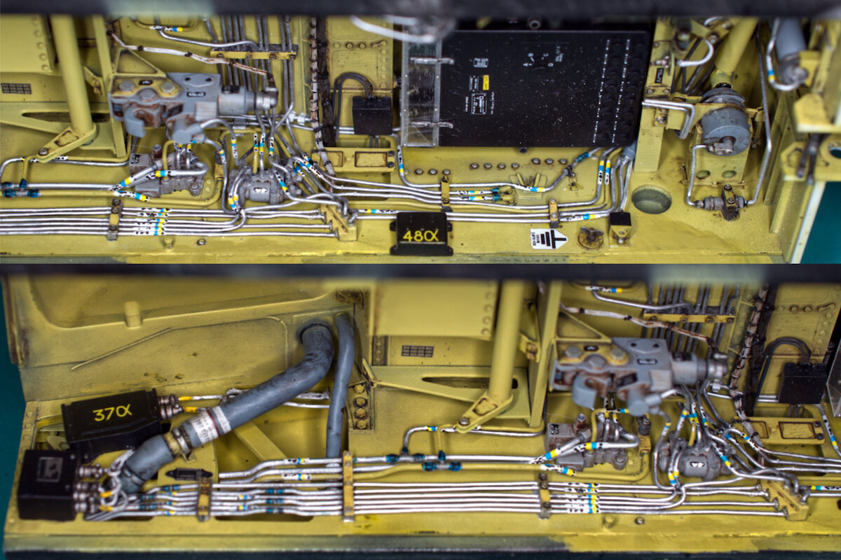
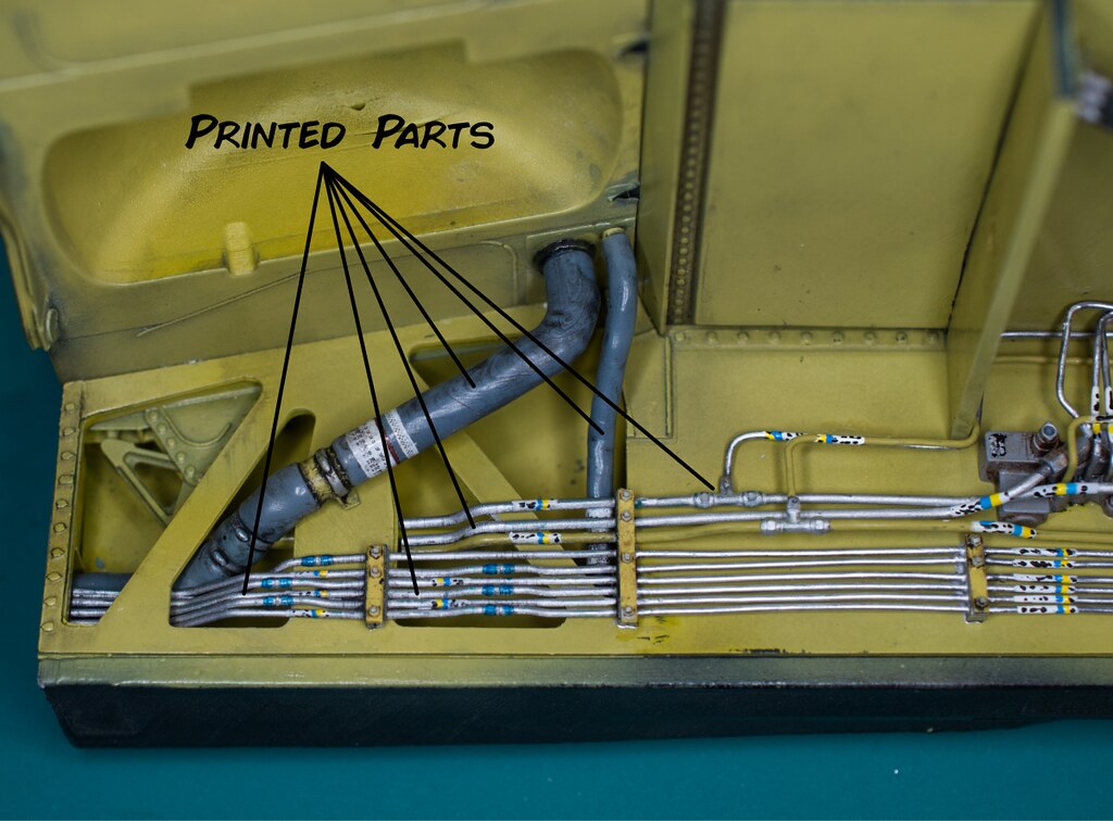
Took some iPhone shots today. The majority of the hydraulic lines are complete for the top of the nose gear well. I’ve added a wire bundle, that several hydraulic tubes will route over, was installed. These tubes required a number of T fittings and check valves to be printed up and pieced together. It’s not an impressive number of tubes installed since my last installment but between fiddly construction and hours of staring at photos to understand where everything connects they consumed that time span. Lastly the torque tube that connects the aft doors to their actuator was installed. There are some hydraulic tubes that will route over this tube necessitating it’s installment now.
On to the photos...


More soon....
Thanks for checking in!
Timmy!
-
Hi guys,
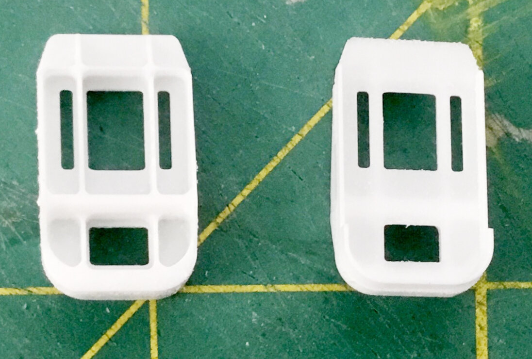
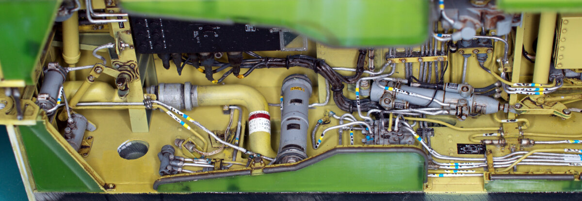
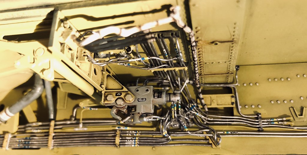
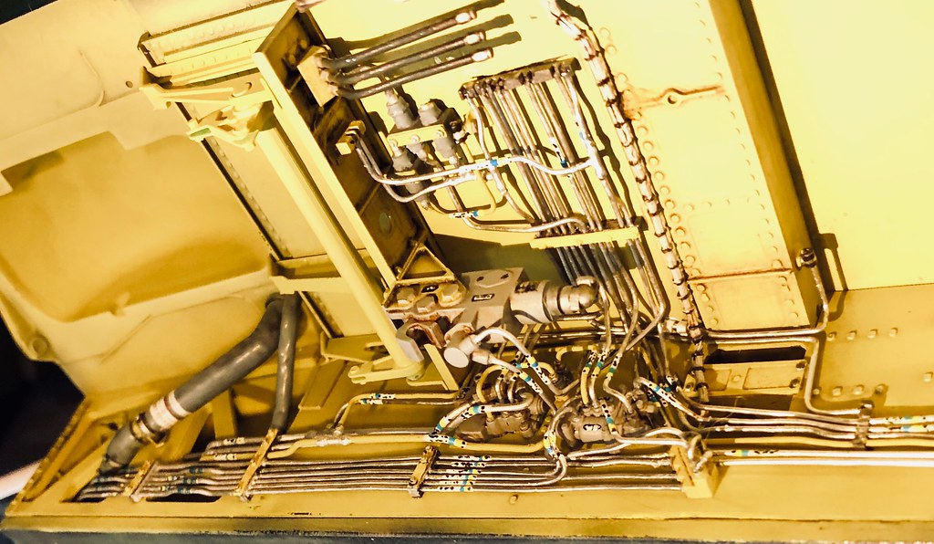
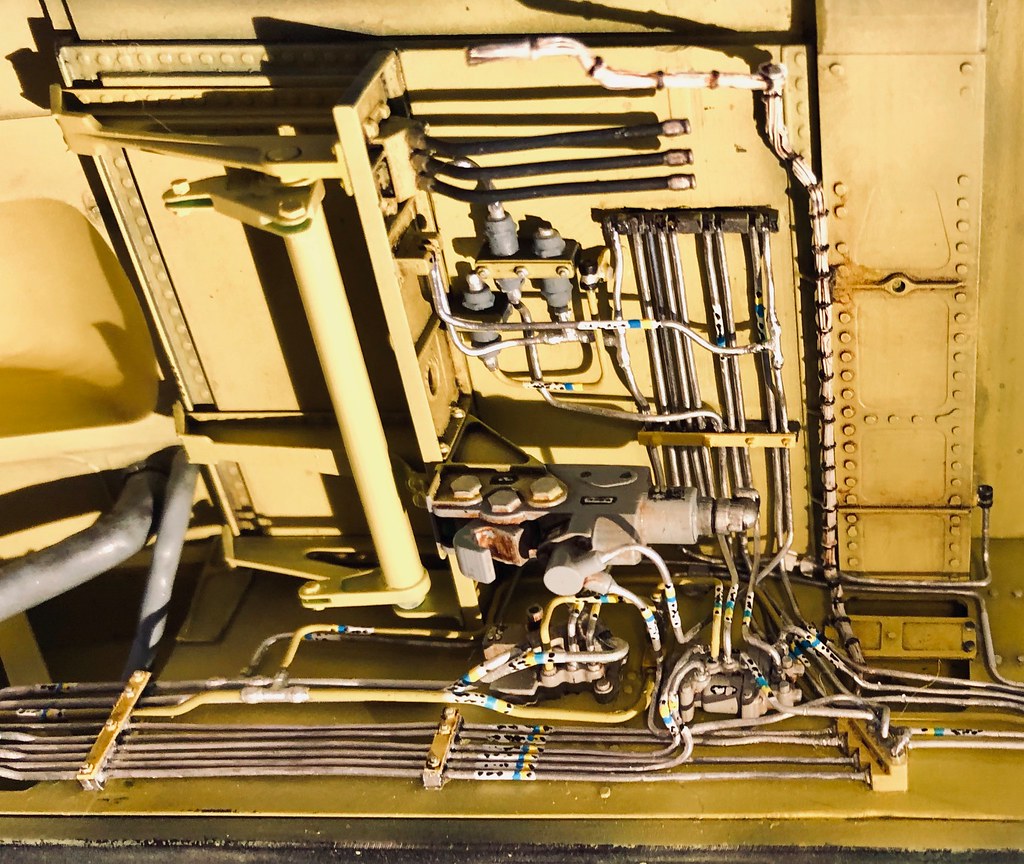
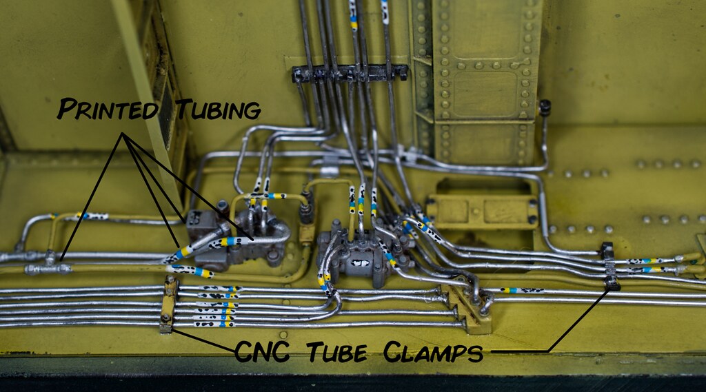
I‘ve started with some assembly and initial layers of detail. The following photos are the left side of the nose landing gear well. This detail is primarily the hydraulic tubing, and insulated environmental system tubing. As a proof of concept idea I chose to try to print sections of tubing. The aft most lines are laterally offset and have connectors that needed to be rendered. Doubting my ability to bend and fashion identical parallel line by hand as well as keeping future production in mind a printing attempt was justified. So the tube sections were modeled in CAD with portions tubing clamps at each end and sent off to my Photon. I did print three copies of each section, as it turned out, all printed successfully but one of the three was perfect.
The remainder of the tubing was fashioned from lead wire. Printed fittings and CNC milled tubing clamps were placed on the side wall using a paper template made from a 2d drawing exported from my CAD software. Hours of studying photographs and tracing one line at a time, I managed to get all the pipes in what I think is the right place. That is to say, every tube end landed on a connection point, no loose ends. I know they are not 100% correct but, without a maintenance pub that shows a trace of each line....I’ve achieved a, let’s say, 98% accurate result.

Here are a few more printed parts. I finally invested in a proper macro lens with a ring flash. I think the photos are much better...two problems though. 1. You can see every microscopic flaw, even though I build with layers of magnification from my cheaters down to 10x jewelers loop. ....and.... 2. I’m working on my f stops for depth of field. So far my shots are hand held, maybe a little less laziness on my part and I should use a tripod and focus merge multiple shots. Irregardess y’all ort git the gist of my progress.


Thanks for checking in!
Timmy!
-
On 4/28/2019 at 6:24 AM, Dutch said:
...What CAD program are you using?...
The original model was begun on Rhino Mac, and is now being brought in and redesigned in Fusion 360. One of the biggest reasons for the switch was the integrated CAM functionality.
Hello again!
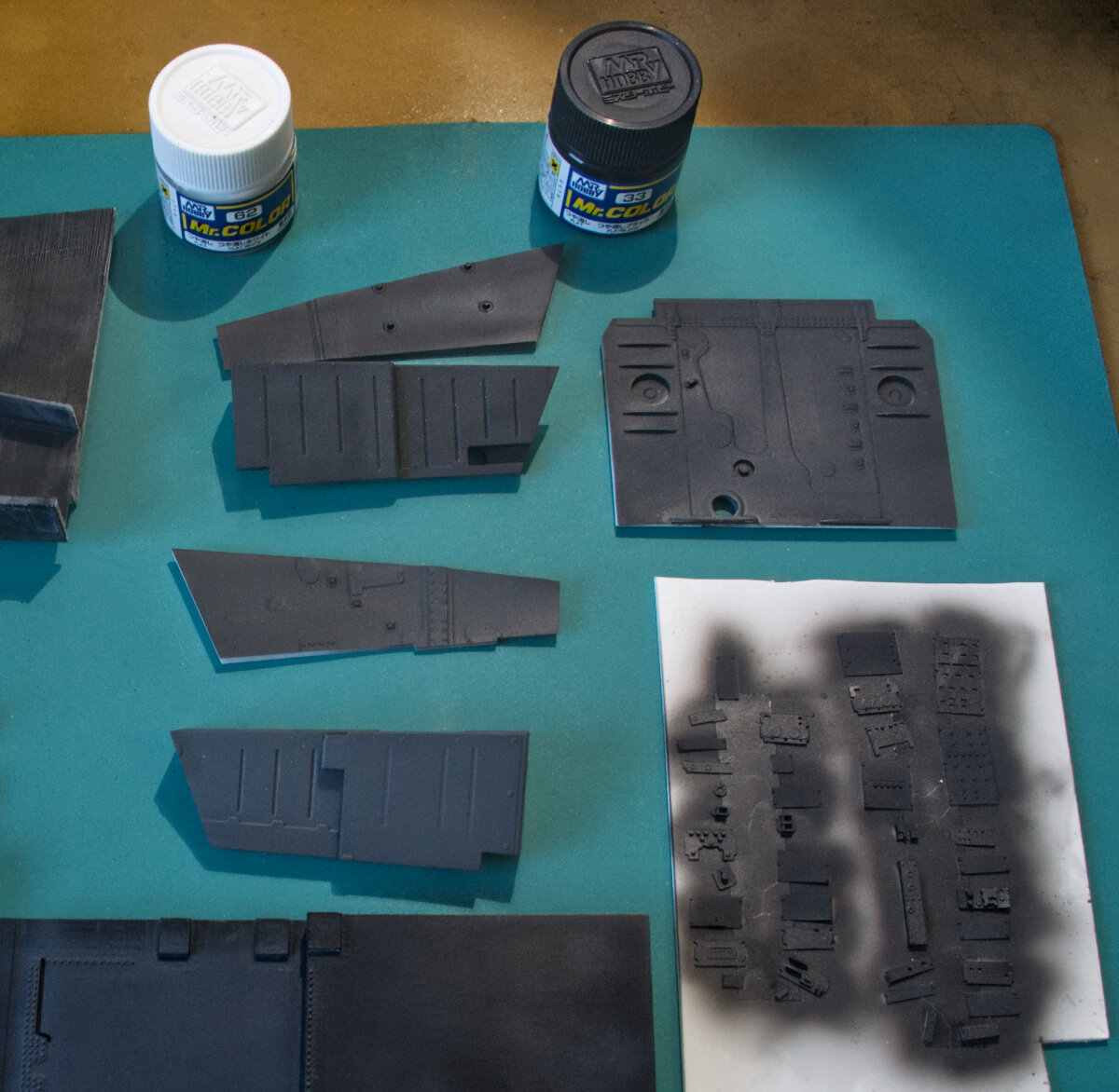
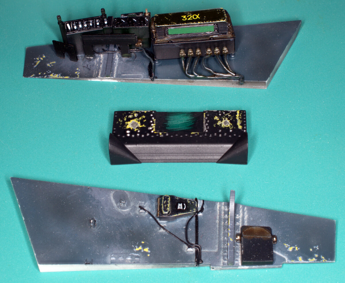
I’ve been busy printing and prepping parts. The skeleton and first layers of detail are ready for final fitting and assembly. Everything received a coat of black epoxy primer, for two reasons to seal the FDM printed parts and fill machine marks and layer lines on the CNC cut, and resin printed parts. I mixed up some chromate color with Tamiya yellow and green and sprayed a base color layer. A few days later I received some MRP paints...I've been looking a paint solution since the demise of Floquil. Great paint, and I super happy with the results. Anyway, I sprayed a thin layer of MRP chromate over the Tamiya color and I was pleased with the mottled effect and overall fidelity of the base color. Details were painted in their appropriate colors, then the parts were sealed with Future. A layer of lamp black and burnt umber oils, thinned with Japan dyer was applied, then promptly wiped away. This dirtied up the surfaces and created a good back ground for the details to come. Assembly is underway, with some printing successes I'm looking forward to share in the next installment
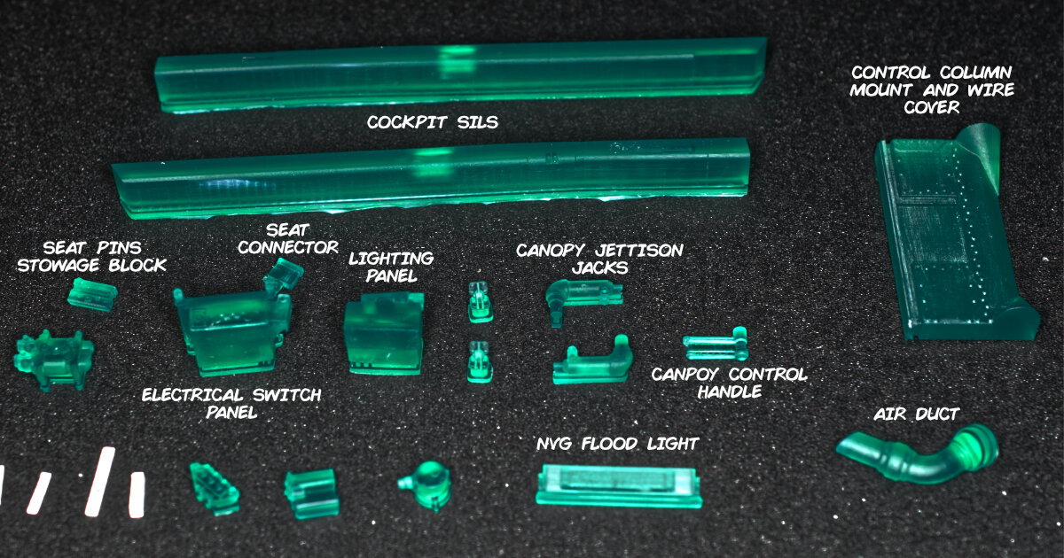
White parts CNC cut acrylic and styrene, green/blue parts are resin printed, and the dark gray part in the middle was CNC cut, top and bottom halves the make up the cockpit floor and nose gear well overhead. The nose gear well half had a printed detail appliqué added.

Primed parts
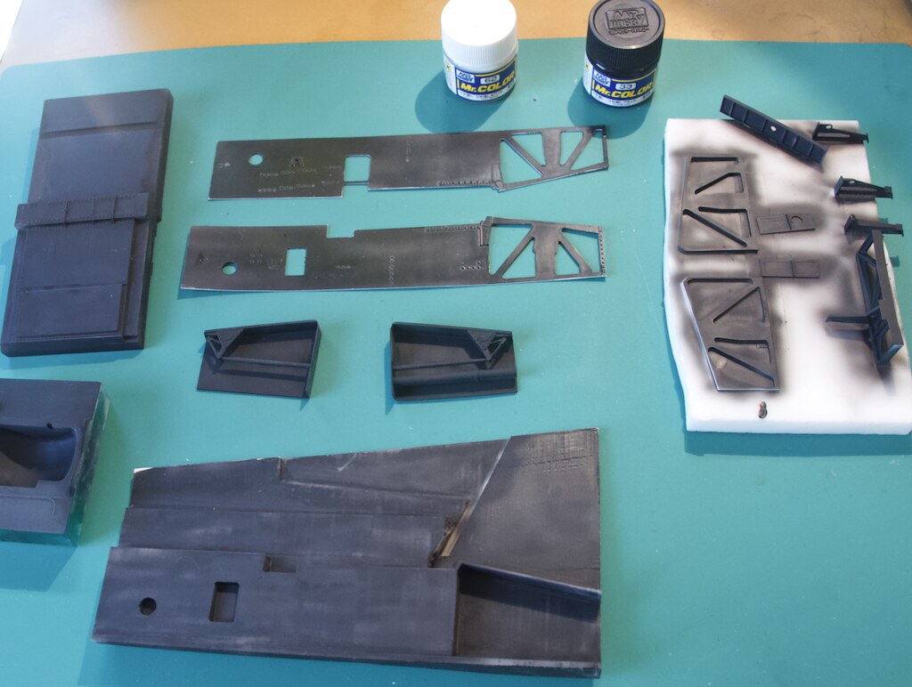
Base Tamiya color

Weathered parts

Detail composites

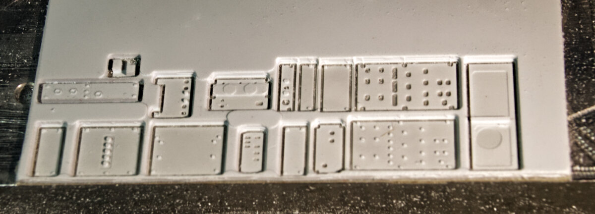
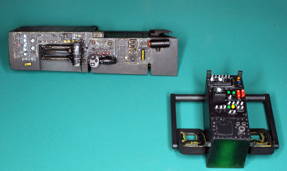
This stuff is coming up. These are the console panels that were cut from 0.040” styrene on the CNC mill.

Thanks for tuning in!
Timmy!
-
It has to do with swept wing aerodynamics and span wise airflow. Bad things like adverse yaw and pro-verse roll happen. Google swept wing aerodynamics if you want to learn more.
In small aircraft straight wing world, a gnarly slip to descend fast or fix that high approach, short of aerobatics...nothing more fun!
Timmy!
-
For anyone willing to attempt this type of conversion, I have uploaded some files to Thingiverse. Some of the parts are meant to be printed on resin type printers and others for CNC milling. Part descriptions will indicate what method best suited for production.
Enjoy and thanks for watching the project.
Timmy!
P.S. Plans will be published at a future date. I'll post here when available.
-
You're warm. The ailerons are deflected. Ailerons deflected normally, there is no cross control. Cross control, very bad in swept wing jets, by the way.
-
Deleted duplicate post
-
Well kids....
I started all over again...
New thread because the old one was just devolving into a endless stream of do overs.
THIS THREAD SHALL NOT BE WHAT CAME BEFORE...THIS ONE WILL BE A FINISHED PROTOTYPE MODEL!!
So a few months back my good friend Paul Fisher lost his home and wonderful workshop to fire in Paradise, CA. I am so happy he and his family escaped and in that light the mention of what comes next seems so trivial.
Paul was in possession of the masters I had completed at the time of the fire so an opportunity to build a better model arose.
Considering the magnitude of the work I previously completed, I started thinking about how to speed up the build. As many of you know I have turned to CNC and SLA type 3d printing to augment the hand building of the model. Until recently I had eschewed the use of FDM type printers due to the inaccuracy of the prints, and significant post processing required after printing model parts. Cost also was a factor, nothing was worth the investment versus the risk of poor parts.
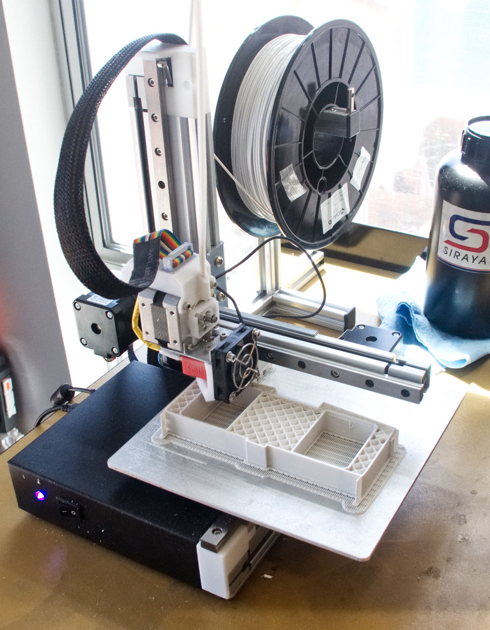
Enter the Tiertime Cetus MKIII. This little printer was cheap, precise and worth a gamble. The main feature that attracted me to the printer was the linear guide rails and bearing blocks. These almost guarantee accurate movement of the axises of the printer. With a price in the $300 US range it was worth a try. With the printer in hand and after some tweaking with the assembly of the printer I managed to print dimensionally accurate parts. One inch cubes were printed and were measured by digital caliper only a few ten thousands of an inch from true, and square adjacent surfaces measured with a machinist's square.
So I ordered up 7,000g of PLA filament and started a-printing.
On a similar journey I ordered up an Anycubic Photon MSLA printer, though this journey was much longer because the Photon required much more significant modification to get true parts. Out of the box it made fantastic parts in terms of detail. However, they parts didn't fit with others, they were skewed in the Z or vertical axis. The modification was much too complex to detail in this post, suffice to say the machine was disassembled, parts were machined true, linear rails and bearing blocks added and a new parts were machined to make it all work. Parts that came out of the machine post modification were exceptional!

Now that I have three machines working simultaneously part production has definitely accelerated the pace of this build.
I have also made some design changes. Outside of getting another chance to improve the model's accuracy, simplifying and streamlining the build has been a chief consideration. So the model will still be "skinned" in aluminum sheet but only where there are removable panels, the remainder of panel detail will be scribed in to a layer of primer paint. PLA is a difficult material to sand and also hygroscopic and needed to be well sealed. I'm using 2 part automotive epoxy paint (paint and hardener) to fill and "glue" the PLA layers together. The result is a surface that is much easier to sand and finish. You can see a few of the PLA parts were the black primer has been applied and finishing has started.
Lastly my machining skills have improved to the point where the acrylic parts now have machined in details, rivets and reinforcing layers etc.
Here's a shot of the parts so far. These parts represent the main components of the fuselage from the nose to the engine faces.

More detailed photos coming as assembly commences. This will be a prototype model, so I will be finishing this one as I go, so you can look forward to finished assemblies going forward.
Thanks for checking in!
Timmy!
-
It’s self adhesive.
-
16 minutes ago, dnl42 said:
Dang! I see this took quite some time to complete, but it's awesome!
 Good thing I'm comfortable with my comparatively schlock modeling skills...
On the wing tip lights. It looks like you prepared the lights, attached them to the wing tip, faired them in, and then masked them to continue on with finishing. Is that right?
Exactly correct, though the wasn't much preparing of the light material. I cut a rectangular cube glued it in, then sanded the whole wingtip to shape. The light has a larger crossection and the wing tip airfoil so you get the bulged appearance. That bulge was all done with light material and filler, blended to the kit wing.
As always thanks so much for following and the kind comments!
Timmy!
-
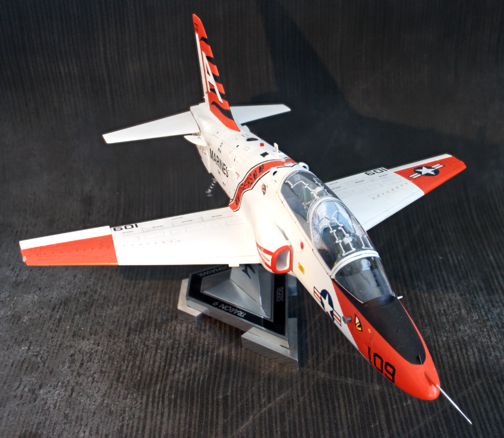
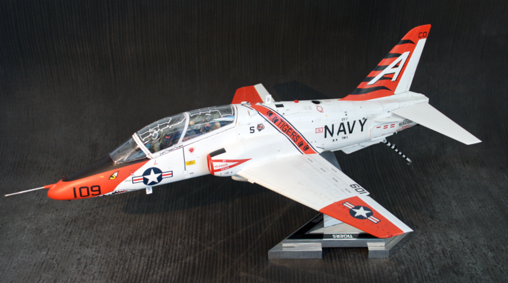
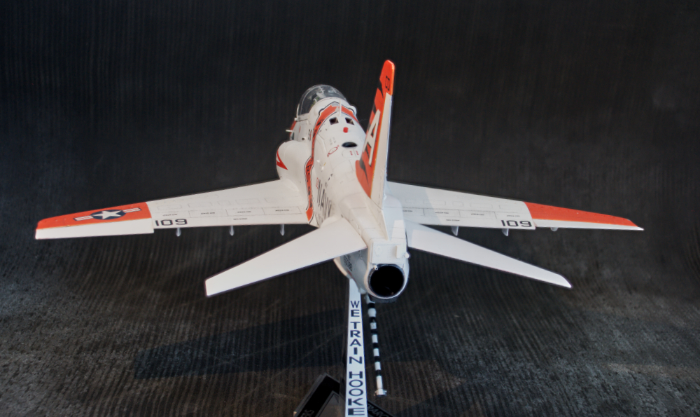
IT IS DONE!!!
I like it, gots some buggers but I learned some new techniques and it’ll look decent on a shelf!
Final build article link HERE!…
Gave the model a name BTW
THE STUDENT’S REVENGE
See if you can figure out why….
Thanks for watching,
Timmy!
-
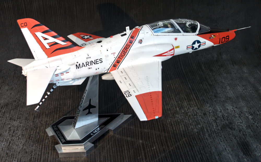
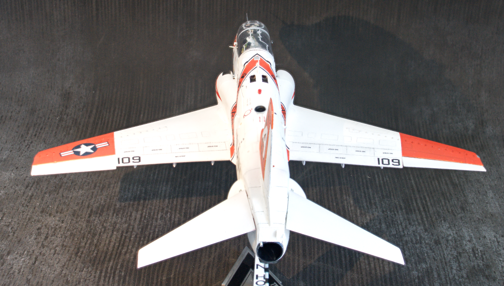
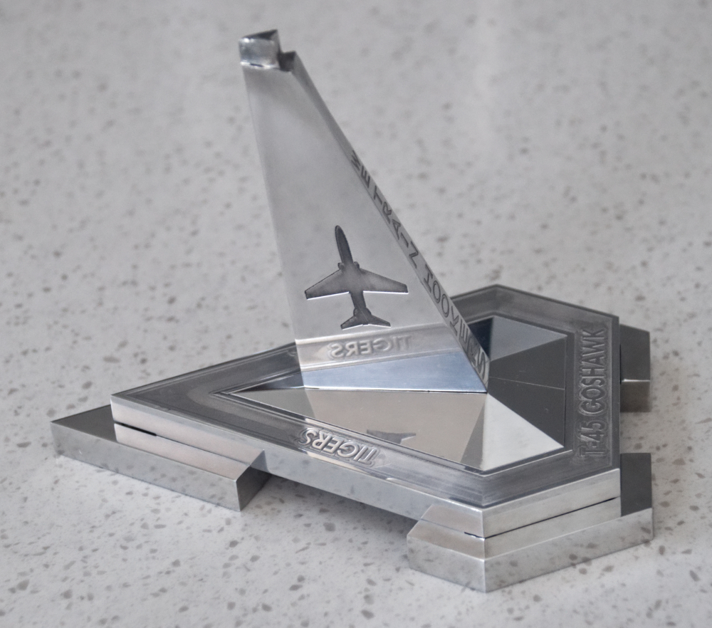
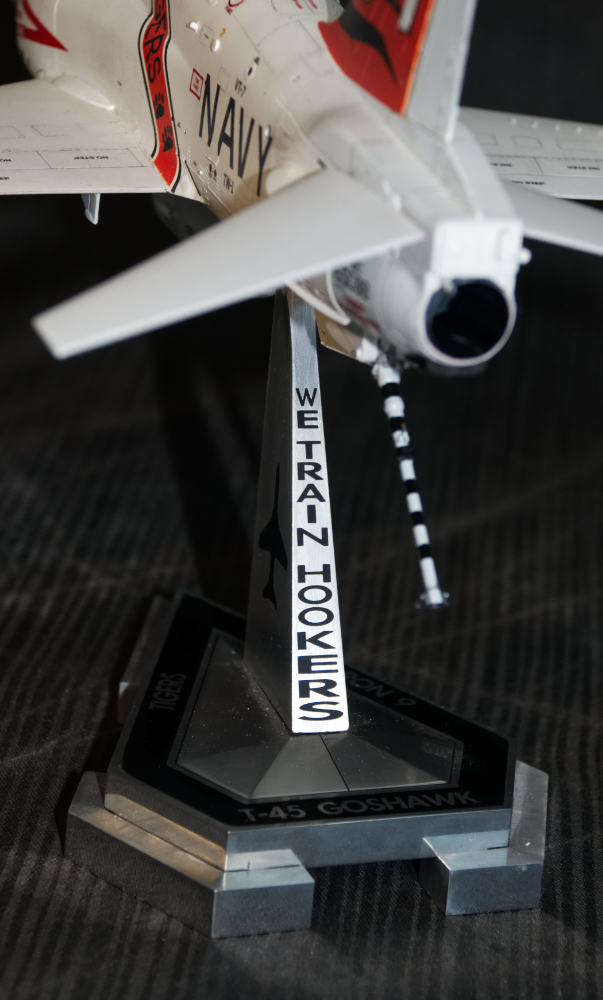
Last details and stand complete!
Last of the details and getting the stand finished up. Full write up found HERE.
For your viewing pleasure.
Thanks for watching,
Timmy!
-
On 7/31/2018 at 9:38 AM, modelmax said:
Wow ma'an! your work is amazing!
Been following from the start... highly educational.
I liked the use of vinyl for detail work. first time I see this technique.
One question... what kit of vinyl do you use?
Thanks, and congrats on superb work.
Ernie A.
Its Oracal vinyl...google search will find many suppliers! Thanks fro the kind comments!!
Cheers,
Timmy!
-
On 7/25/2018 at 7:08 PM, lockheed2004 said:
Is “Arrestnig Hook” unique to the aircraft? I didn’t see that covered in your article, just curious, or if you had an easy to fix typo on your decal.
What? Are you sure??
Thanks!
Timmy!
F-4EJ改 KAI: Tamiya 1/32nd Scale
in In-Progress Pics
Posted
Thanks. It's Gunze Sangyo Mr. Epoxy Pro-H. It has a much finer grain and yes it is much smoother and easier to work than Apoxie Sculpt.