Vidar_710 Posted April 1, 2017 Share Posted April 1, 2017 I knew you wouldn't be able to help yourself! ;-) They look awesome!!! Molding would be a snap if you make the vertical mounts and forward braces one part, then the two different inboard braces separate. I'll assemble them on the model. I plan to cast them in white metal or hard resin. Will the tongue brackets that the braces bolt to be in the side braces, or will I need to just make them from sheet styrene? Tracy Quote Link to post Share on other sites
crackerjazz Posted April 16, 2017 Author Share Posted April 16, 2017 (edited) Hi Tracy, sorry for the delay, I was having a little trouble matching/aligning some views for the front mount. And the pull of the Tomcat was too strong (was kind of working on that, too, to prevent burnout I was trying to match the rear view line drawing with the sideview and couldn't get them to match. The 4.46 deg. mentioned here threw me off. Until i found a portion of the blueprints showing the ferry position and overlayed the rear views on it. It's clearer to me now. The front mount can kneel lower that what's shown in the rear view. BTW, your question about the tongue brackets -- they'll be there when I separate the parts. They'll be really tiny, though -- hopefully they'll still be recognizeable. Edited April 16, 2017 by crackerjazz Quote Link to post Share on other sites
Vidar_710 Posted April 17, 2017 Share Posted April 17, 2017 No worries... I'm not one to throw stones in glass houses. I bounce around project to project as well. Keeps the project fresh when you can walk away from it and start fresh without completely leaving the hobby. Looking forward to seeing what you come up with in the forward mount. I am extremely glad you have your own 1/100 747 there to reference from - cuts down on the difficulties of explaining details via text. ;-) Tracy Quote Link to post Share on other sites
crackerjazz Posted May 29, 2017 Author Share Posted May 29, 2017 Hi, just getting back to this, sorry. Project isn't dead ...... work is getting in the way of hobby-time :) I'm mirroring both sides for now but will correct later. Only the starboard side should have the knuckles (I wonder why). Quote Link to post Share on other sites
Vidar_710 Posted May 29, 2017 Share Posted May 29, 2017 (edited) Looking terrific! The drawings as a guide are awesome. How well does the shape, and diameter of the Entex 74 fuselage match the drawings? Do they match, or do you expect any post adjustments after the modeling is done? When I get home off my current trip, I'll share the 3D printed additions I already have for this project: Shuttle tail cone 747 engines Vertical tip stabs for the horizontal tail surfaces Kreager leading edge flaps, and trailing edge flaps. Now if we can get Hotdog to rescale the top side shuttle decals for the Tamiya kit! ;-) Tracy currenly, l've been the most motivated with my Large Starship Excelsior scratch build. Edited May 29, 2017 by Vidar_710 Quote Link to post Share on other sites
crackerjazz Posted May 31, 2017 Author Share Posted May 31, 2017 Compared to the drawings, the Entex/Doyusha height at this point is off by a few mm -- could be the drawings or the kit itself : ( I'll have to measure the width at the attachment points of the forward mount and make adjustments to the 3D model if necessary. Quote Link to post Share on other sites
Vidar_710 Posted June 22, 2017 Share Posted June 22, 2017 For the longest time, I thought the forward mounts actually attached to the fuselage right into the aft window ports in the dome. Looking back I discovered why... The old 1/144 scale Revell Shuttle/SCA kit I built as a kid made that the gluing point for the forward mounts. LOL Tracy Quote Link to post Share on other sites
Trojan Thunder Posted June 22, 2017 Share Posted June 22, 2017 1 hour ago, Vidar_710 said: For the longest time, I thought the forward mounts actually attached to the fuselage right into the aft window ports in the dome. Looking back I discovered why... The old 1/144 scale Revell Shuttle/SCA kit I built as a kid made that the gluing point for the forward mounts. LOL Tracy I'm building that kit now and left those windows open for the same reason, looks like I will fill them and make new mounts. Quote Link to post Share on other sites
johnbuck Posted July 6, 2017 Share Posted July 6, 2017 Extraordinary CAD work / search cracker jazz..............what a talent............ Look forward to viewing the printed piece. Cheers johnB Quote Link to post Share on other sites
crackerjazz Posted July 6, 2017 Author Share Posted July 6, 2017 This one, too, hehe. Really appreciate the kind words. But I was getting cross-eyed and all trying to align the drawings. And my 3D touch must be fading --- I couldn't get some stuff right. Also I'm really worried about the parts -- being ant-sized -- if they'll actually pull through the printer with details intact. I'm just worried it will all come to nought. A little break should do some good. But thanks for the support, guys. Quote Link to post Share on other sites
Vidar_710 Posted July 8, 2017 Share Posted July 8, 2017 CJ, I have no problem with you using a little creative licensing to adjust the parts to fit the model. For all we know, both the model and the drawings could be off. As far as your concerns about it being printable... I think you'll fine it'll be OK. Amongst the other 3D printed parts I've had made for this project, the most intensely detailed is the engines for the 747. Each stator and vain in the N1 Fan section, as well as the turbine section seen through the exhaust is beautifully printed separately. These mounts in 1/100 scale should be awesome... 1/144 or smaller is anyone's guess. The diameter of the forward mounts shouldn't be a problem, and their strength is moot due to my plans to mold and cast them in hard resin. I agree... stepping away and coming back with a fresh perspective is always a good thing. Being an airline pilot, I have the opportunity to be forced in to doing just that. It has been instrumental in regards to my Large scratch-built U.S.S. Excelsior NX-2000 project. I'm in full steam on that, getting close to finishing the masters for vacuum forming new clear hull parts (now that my large vacuum for table has arrived.) Tracy Quote Link to post Share on other sites
Vidar_710 Posted July 28, 2017 Share Posted July 28, 2017 (edited) CJ, Do you have an expected measurement from the crest of each aft mount. I'm going to cut out the shapes and scratch built the recessed panels where the ET, and the 74 mounts insert into their sockets in the belly of the shuttle. If you don't want to do the forward mount, I think I can manage to scratch build it. Let me know when you're ready to submit the aft mount parts to Shapeways, and I'll go ahead and get them printed so I can't get them into clay and rubber for casting. Tracy Edited July 28, 2017 by Vidar_710 Quote Link to post Share on other sites
crackerjazz Posted July 28, 2017 Author Share Posted July 28, 2017 (edited) Hi Tracy, no, don't scratchbuild it. Just need to motivate myself and focus on one project at a time. And there are some difficult aspects of the 3d-modelling that bog me down just worrying about them such as when I'll finally have to break them apart -- and I seem to get overwhelmed. And those irregularly-shaped forward mount fairings -- how do I model those? I really have to take it one step at a time -- a scrum board might help. Ok, CJ, take a deep breath, exhale slowly and let's begin! We can do this! Crest to crest = 51.94mm Actually, don't start boring holes into the shuttle's belly just yet. I have to measure the fuse's width at that spot as it might not match the drawing's 51.94 stance. Need to leave for work but let me get back to you tonight. Just need to do some more measurements on the kit's fuse. Edited July 28, 2017 by crackerjazz Quote Link to post Share on other sites
Vidar_710 Posted July 29, 2017 Share Posted July 29, 2017 OK, I'll hold off. I finally found a guy that has the option of early or late Shuttle paneling decals for the top of the Tamiya kit... ordered the late version. I like Hotdog's bottom set in combination with this set using the best characteristics of both. The open panels where the connections are made to the ET/747 are included, and very nicely done. Having everything I need to start has lit a fire under my arse. ;-) Tracy Quote Link to post Share on other sites
crackerjazz Posted July 29, 2017 Author Share Posted July 29, 2017 (edited) So that's 46.83mm on the model. If we follow 51.84mm crest-to-crest the base of the mount would be hanging too low on the sides. We need to follow the 12.69 mm distance from the top (as viewed from the side). Just curious, could you measure the open panels (center to center) on the decals for the rear mounts? Edited July 29, 2017 by crackerjazz Quote Link to post Share on other sites
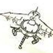
crackerjazz Posted July 29, 2017 Author Share Posted July 29, 2017 Quote Link to post Share on other sites
spaceman Posted July 29, 2017 Share Posted July 29, 2017 (edited) Fantastic 3D-Modeling on a very high level, which proves that you seemingly master your Solidworks playfully, simply awesome! I wish I could do that too ... Edited July 29, 2017 by spaceman Quote Link to post Share on other sites
X-Plane Fan Posted July 29, 2017 Share Posted July 29, 2017 Looking great! Can't with to see the actual parts when they're printed. Quote Link to post Share on other sites
Vidar_710 Posted July 30, 2017 Share Posted July 30, 2017 CJ, I'm currently on day one of a 4-day trip. I'll measure the graphics, and even post pics -if you want- when I get home. I took photos of the Atlantis hatches while visiting the Northern Smithsonian in D.C. They really did an awesome job recreating that detail. Tracy Quote Link to post Share on other sites
Vidar_710 Posted August 16, 2017 Share Posted August 16, 2017 (edited) Sorry for taking so long. Days between trips too short, and still in "Full Tilt Boogie" on the U.S.S. Excelsior NX-2000 project.. Here's a measurement on the decal for the receptacle ports for the mounts. It's showing 1.33cm apart for the mains. I'm not just going to apply the decal to the belly of the shuttle. I am going to cut the panels in for their recessed characteristics, and use these graphics where they are suppose to go. I'm also gonna make the doors as well, then apply the graphics to them. Sooo, this distance is not in stone. I'll place them where they need to be for the 74 to meet the shuttle properly. Edited August 16, 2017 by Vidar_710 Quote Link to post Share on other sites
niart17 Posted August 16, 2017 Share Posted August 16, 2017 Guys, this is some amazing work on these mounts. Super super impressed. Vidar, I do want to note one thing though. in that last pic you posted, the caliber to my eyes looks like it's saying 1.330 inches, not CM. Is that "in" not what the scale is set to? Just an observation. Can't wait to see all this come together. Bill Quote Link to post Share on other sites
Vidar_710 Posted August 16, 2017 Share Posted August 16, 2017 (edited) oooooooOOOOOPS! You're right! and when you're right, you're right, and you ARE right! In my defense, I finally remembered to do this after getting home from my last trip at 3AM. I was spent! Here it is in metric... My pic I took under Atlantis at the Smithsonian Like I said earlier, these recesses will be cut in, and the doors will be scratch from thin styrene with these graphics applied to them. Tracy Edited August 16, 2017 by Vidar_710 Quote Link to post Share on other sites
crackerjazz Posted August 16, 2017 Author Share Posted August 16, 2017 (edited) Thanks, Tony, Manfred, Bill! Tracy, thanks! Hmmm....that's a huge difference from our 59.4 crest-to-crest measurement : ( Can you try marking 59.4 on the shuttle's belly? The decals must be right so where did we go wrong? 34mm seems too close for the main mounts to sit right on the Doyusha kit but I'll check the fuselage tonight. Edited August 16, 2017 by crackerjazz Quote Link to post Share on other sites
habu2 Posted August 17, 2017 Share Posted August 17, 2017 (edited) On 8/15/2017 at 10:30 PM, Vidar_710 said: Sorry for taking so long. Days between trips too short, and still in "Full Tilt Boogie" on the U.S.S. Excelsior NX-2000 project.. Here's a measurement on the decal for the receptacle ports for the mounts. It's showing 1.33cm apart for the mains. I'm not just going to apply the decal to the belly of the shuttle. I am going to cut the panels in for their recessed characteristics, and use these graphics where they are suppose to go. I'm also gonna make the doors as well, then apply the graphics to them. Sooo, this distance is not in stone. I'll place them where they need to be for the 74 to meet the shuttle properly. That distance you are measuring is between the fuel & oxidizer inlet ports - not the structural mounting points. Those small circles in the upper outer corners of the decal are where the SCA (and ET) connect as a load bearing point. edit: see the callouts for "ORBITER - EXTERNAL TANK AFT ATTACH POINT" on the drawing at this link: http://web.archive.org/web/20001002192048/http://www.spaceflight.nasa.gov:80/shuttle/reference/sodb/2-5a.pdf I found another drawing that shows the attach points are +/- 57 but no units are given. I doubt that dimension is in inches because I know the doors are 50" x 50" with 4" radiused corners, making the attach point spacing closer to 200" Edited August 17, 2017 by habu2 Quote Link to post Share on other sites
Vidar_710 Posted August 17, 2017 Share Posted August 17, 2017 (edited) I think I may have found the problem, The decals sent may be in 1/144 scale. I've sent the maker an email to confirm my findings. Another thing is, your measurements may be incorrect as well. I took some picks of the 74 fuselage and a pick of the real SCA to corroborate my findings.. 1. The decals are defiantly too small 2. Your measurements would put the mounts bases almost down on top of the passenger doors, so... too wide. 3. Using a image off an SCA, I extrapolated that the mounts are about a "half door" high above the actual door positions. This would place the base of the mounts where they attach to the fuselage at, or just a tad above the raise panel line that runs longitudinally down the fuselage just above all the doors, making the distance between the ports about 49.5mm. Defiantly decal too small a scale. Real SCA mount posit. half a door above PAX doors. Measurements, Top: CJ's measurement, Middle: decals measurement. Bottom: my measurement (raised panel line to raised panel line) Oblique angle. Take note CJ how far down to the door the mount would be with your measurement. I think for the purpose of this 1/100 scale project, that the best measurement for separating the tips of the "balls" or receptacles in the belly that fit into the shuttle's panels is 49.5mm. Thoughts CJ? Edited August 17, 2017 by Vidar_710 Quote Link to post Share on other sites

Recommended Posts
Join the conversation
You can post now and register later. If you have an account, sign in now to post with your account.