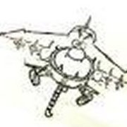
crackerjazz Posted August 26, 2017 Share Posted August 26, 2017 (edited) Aigore inspired me so much I had to pull out one of the Corsairs from the stash. I'll try to scratch a thing or two but build it mainly OOB. The kit's got a pretty good instrument panel. I had to flare the ends of the canopy breakers by cutting off the lower half and replacing with a piece of styrene. I nicked the edges of the cushion with the cutter blade for effect as it looked too solid. A nod to Aigore. I just had to do the same. Will add this later. Edited August 26, 2017 by crackerjazz Quote Link to post Share on other sites
Janissary Posted August 26, 2017 Share Posted August 26, 2017 That sanding stick idea is neat. What exactly is that? Quote Link to post Share on other sites
crackerjazz Posted August 26, 2017 Author Share Posted August 26, 2017 Thanks, Jannisary! It"s a 10mm styrene rod : ) Quote Link to post Share on other sites
my favs are F`s Posted August 26, 2017 Share Posted August 26, 2017 Awesoooome. Let`s get back to the 80`s... :) It will be awesome following this tandem build (with the Intruder). Enjoy the assembly and keep us posted! :) Quote Link to post Share on other sites
kike Posted August 27, 2017 Share Posted August 27, 2017 Oh yeah! another great plane in the making!!! Quote Link to post Share on other sites
Aigore Posted August 27, 2017 Share Posted August 27, 2017 Great work, mate! And that cockpit looks awesome :D Quote Link to post Share on other sites
crackerjazz Posted August 28, 2017 Author Share Posted August 28, 2017 Hi MFAF, kike, Aigore, thanks, guys! The sidewall of the kit was a bit bare. I covered it with "fabric" like I see in some photos. Drilling out holes for the internal bracing for in-flight mounting. I need to make sure they're in there before I close up the fuse. I hope I know what I'm doing. I carried this out with nary a plan. These rods won't really be visible and the diameter of the final holes on the sides of the fuselage won't be as big as these but just big enough for the wires to go through just like on the Tomcats. I took some sprue to a candle and fixed the rear rod to the wheel bay, making sure I didn't get any on the fuse -- or I'll be in for some warped panels. Quote Link to post Share on other sites
Aigore Posted August 28, 2017 Share Posted August 28, 2017 Neat work! In-flight display? Wow going to look awesome.....what's the set up? Quote Link to post Share on other sites
crackerjazz Posted August 28, 2017 Author Share Posted August 28, 2017 Hi Aigore, thanks! Oh --- nothing fancy, just maybe the same way I mounted the F-14s, with wires going into the starboard side of the fuselage so they won't be too visible. Quote Link to post Share on other sites
A-10 LOADER Posted August 28, 2017 Share Posted August 28, 2017 Nice work so far crackerjazz. What happened to the Tomcat build ?? Steve Quote Link to post Share on other sites
okthree Posted August 28, 2017 Share Posted August 28, 2017 Nice work on the intake. It looks flawless. Quote Link to post Share on other sites
crackerjazz Posted August 30, 2017 Author Share Posted August 30, 2017 (edited) Hey, thanks, okthree, Steve! Not too proud about my slow progress on the F-14s so I haven't posted updates recently. I meant on closing up the canopies but there's still the front canvas cover to take care of -- which I've done and painted up but now I'm not sure about the color. And that's what's eating at me and preventing me from closing it up. And I didn't want to show any photos because I'm sick of my own cockpit work : ( But thanks for asking. Actually, let me update that thread and throw the question out there about the canvas boot. Edited August 30, 2017 by crackerjazz Quote Link to post Share on other sites
Mr.Happy Posted August 31, 2017 Share Posted August 31, 2017 Great start to a great subject 👍 I'll be tuning in for the next update and great job on the intake✅ Cheers, Mr.Happy(In name only) Quote Link to post Share on other sites
crackerjazz Posted September 2, 2017 Author Share Posted September 2, 2017 (edited) Hi Mr. Happy, I'm glad you like it! I turned my attention to the main landing gear bay doors. The first one showed a lot of promise. Glued on the bottom door and things quickly turned sour. Their edges didn't meet. I soon realized these bay doors weren't meant to go on in the closed position. Wrapped some wire and glued the edges together. There's still that ugly gap. And triangular shaped even, which might derail the scribing tool later. I was toying with the idea of just sand the ends to have a nice rectangular opening but then I wouldn't be able to bond the edges together. I was thinking the little door would be a breeze. But it's shape was too arched that if you tried to align the ends flush to the body the middle arch juts out, and if you push down the middle the lower end falls inside. So I tried to straighten it up with the long-nose and this is the best I could come up with. Will let the sandpaper take care of things. The port side was worse. The lip for the bottom door is too low so there's a dip on the left edge when you glue it on which I would have to fill with putty. I had to brace the back with something so I can fill the gaps. So I opened up the gear bay panels. And filled the door edges with Apoxie Sculpt before I went to bed. And started sanding 8 hours later. In hindsight I should have just glued on some styrene bulkhead for the door to conform to the fuse's shape instead of using lots of putty outside. And I hope the Apoxie Sculpt lends itself well to scribing. I've tried other putties before but they tend to crumble when scribed. Will need a little more elbow grease to feather the putty but looks better now. Thanks for stopping by! Edited September 2, 2017 by crackerjazz Quote Link to post Share on other sites
Aigore Posted September 2, 2017 Share Posted September 2, 2017 Hard work indeed ! You will beat this kit into submission! :D Quote Link to post Share on other sites
Wolfgun33 Posted September 4, 2017 Share Posted September 4, 2017 Nice work! I hate that the gear doors don't fit closed. Quote Link to post Share on other sites
crackerjazz Posted September 7, 2017 Author Share Posted September 7, 2017 (edited) Hi Aigore, Wolfgunn, thanks! Yeah the main doors take a bit of work. Feathered... I decided to work on the other A-7, too. This door fits nicely, once you scrape off some material from the right side. Painting the other cockpit. I messed up the IP of the other Corsair. I painted it but wasn't too happy so I wiped it off using lacquer thinner so I can start over. And the plastic turned into a gooey molten mess. I don't know what I was thinking. I'm always careful about lacquer thinner getting onto the model but clearly I wasn't thinking in this case. I should've taken a photo of it but couldn't find it in the waste basket anymore. A while back I picked up an Aires cockpit which turned out to be for the Hobby Boss kit and wouldn`t fit the Hase fuselage. I'll just use the IP for the other A-7. Painted her up. On the second cockpit I found that I could flare the ends of the canopy breakers just by making the same cut on the ends and flaring them but not breaking them off totally. Edited September 10, 2017 by crackerjazz Quote Link to post Share on other sites
A-10 LOADER Posted September 7, 2017 Share Posted September 7, 2017 Things are taking shape, nice work on that IP. Steve Quote Link to post Share on other sites
CaptainObvious Posted September 9, 2017 Share Posted September 9, 2017 That's some really nice work on the cockpits and intake. The main gear doors look painful though you seem to be beating them into submission. Great job! Quote Link to post Share on other sites
crackerjazz Posted September 9, 2017 Author Share Posted September 9, 2017 (edited) Thanks, Steve, CaptainObvious! : ) Took a break from the doors and wrestled with a pilot figure to get him to fit into the seat. Got a good batch of figures that I could use, c/o Darren - thanks! This one's a Tamiya-Hasegawa combo. Have to check if I need to modify the helmet. And there are 2 hoses right now, one will have to go. Does anyone know where the hose connects to inside the cockpit? Edited September 21, 2017 by crackerjazz Quote Link to post Share on other sites
my favs are F`s Posted September 9, 2017 Share Posted September 9, 2017 Very very cool-looking IP. Dark and sharp! Quote Link to post Share on other sites
Aigore Posted September 9, 2017 Share Posted September 9, 2017 Great looking IP! Quote Link to post Share on other sites
JohnS Posted September 9, 2017 Share Posted September 9, 2017 (edited) 6 hours ago, crackerjazz said: ... Does anyone know where the hose connects to inside the cockpit? ... Here are links to photos of the Escapac IC-2 & IG-2 ejection seats. http://www.ejectionsite.com/texans/ig2.jpg http://www.ejectionsite.com/texans/ic2front.jpg The oxygen hose connection is located at the bottom of the seat back on the right side (the pilot's left side). Is this what you're looking for? Edited September 9, 2017 by JohnS Quote Link to post Share on other sites
crackerjazz Posted September 9, 2017 Author Share Posted September 9, 2017 (edited) Aigore, MFAF, thanks! Hey, John, thanks so much. Yes, that's what I needed. I was under the impression that the hose from his oxygen mask connects directly to that hose on the starboard-side console that I see on Aires A-7 cockpits. But then I thought if that were true, then it would rip the mask right off his face if he ejects. So it makes sense that it connects to something on the seat itself. What is that hose on the console for, by the way? Edited September 10, 2017 by crackerjazz Quote Link to post Share on other sites
JohnS Posted September 9, 2017 Share Posted September 9, 2017 2 hours ago, crackerjazz said: ... What is that hose on the console for, by the way? ... Good question! I did a quick search but can't find a photo of those hoses. Here's what I did find; http://www.arcforums.com/forums/air/index.php?/topic/127872-i-need-a-7e-cockpit-photos-help/ http://img.photobucket.com/albums/1003/superheat162/AC photos/aDSCN1180.jpg Here's a link to a copy of the A-7D Flight Manual including photos & outline drawings of the cockpit panels. See Page 27, Figure 1-5 showing the righthand panel. http://www.avialogs.com/index.php/en/aircraft/usa/vought/a-7corsairii/to-1a-7d-1-a-7d-corsair-ii-flight-manual.html John Quote Link to post Share on other sites

Recommended Posts
Join the conversation
You can post now and register later. If you have an account, sign in now to post with your account.