Craig Baldwin Posted November 4, 2017 Share Posted November 4, 2017 You've chosen a nice way to add those details. May I add an image that shows the burner can detail from the outside, forward. The forward sections were welded segments and aft section added on with bolts and screws. The weld seams were ground down smooth. Excellent detailing, if you have any questions I would be happy to help if I can. Quote Link to post Share on other sites
crackerjazz Posted November 4, 2017 Share Posted November 4, 2017 Hey, you've got some good stuff going here! Very nice scratch/detailwork! Quote Link to post Share on other sites
Giovanni Posted November 4, 2017 Author Share Posted November 4, 2017 Hi! Thank You for kind words... 3 hours ago, Craig Baldwin said: The forward sections were welded segments and aft section added on with bolts and screws. The weld seams were ground down smooth. Thank you for the useful photo Craig. So to be accurate one should fill the engraved detail and reproduce the seams with paint... But this means adding time to this project.... I'm really tempted to leave the engraved detail and just add some bolts.... Do you think you can forgive me if I choose the easier way? Quote Link to post Share on other sites
Craig Baldwin Posted November 4, 2017 Share Posted November 4, 2017 1 hour ago, Giovanni said: I'm really tempted to leave the engraved detail and just add some bolts.... Do you think you can forgive me if I choose the easier way? We must always make best use of our limited time, I'm enjoying your take on the project and I'm sure the results will do this kit well. Happy Modelling Quote Link to post Share on other sites
Giovanni Posted November 7, 2017 Author Share Posted November 7, 2017 (edited) Hi! Tonight some riveting on the exterior: As Craig said before on the real thing the surface was smooth and rivets were levelled bolts and not "holes" as I have done. On the ring I gained a better result as you can see in the last photo. I can try to fix the remaining later with some Mr. Surfacer. More updates soon. Bye Giovanni Edited November 8, 2017 by Giovanni Quote Link to post Share on other sites
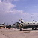
Giovanni Posted December 6, 2017 Author Share Posted December 6, 2017 Hello dear modelers! had few time for going on this recently. Just had the interior of the exhausts painted: I have a question for real experts... Looking at this picture of a preserved airframe I noticed the burner rings aren't vertically oriented but slightly rotated clockwise of same degree. See the red lines. I performed a lot of researches on books and on the web but cannot understand if this is common to all f-101b or to some batches. I thought it could be also an error somebody made while assembling the airframe for display. Does anyone have a picture of this area of an operational airframe to share or have an answer for this? Thank You in advance for helping me! If this can help I'm going to represent this particular aircraft: Thank You! Bye Giovanni Quote Link to post Share on other sites
Craig Baldwin Posted December 6, 2017 Share Posted December 6, 2017 27 minutes ago, Giovanni said: Does anyone have a picture of this area of an operational airframe to share or have an answer for this? If this can help I'm going to represent this particular aircraft: Beautiful looking exhausts. Sorry I can not help you with your questions about the Exhaust/Afterburner question. It's so dark up there it would be hard to find references. I would think most of the engine was still intact on a display aircraft like that as without a large modification it would be a lot of work just to hang the burner section in the aircraft for display. Note 2 things on the reference picture of aircraft 70308 (57-0308). Note on the upper leading edge of the vertical stabilizer a small tube open to the front. If I remember correctly it was for the horizontal stab system and not present on some F-101's. The second is the inlet for the airconditioning system that is just above the left nose gear door. This aircraft, it is flush and it may be a raised on the kit. I am not sure if you were aware of these two items but I thought I would mention it. There were actually few differences in the batches of aircraft of F-101B's. This build is great. Quote Link to post Share on other sites
Giovanni Posted December 6, 2017 Author Share Posted December 6, 2017 17 minutes ago, Craig Baldwin said: Beautiful looking exhausts. Sorry I can not help you with your questions about the Exhaust/Afterburner question. It's so dark up there it would be hard to find references. I would think most of the engine was still intact on a display aircraft like that as without a large modification it would be a lot of work just to hang the burner section in the aircraft for display. Note 2 things on the reference picture of aircraft 70308 (57-0308). Note on the upper leading edge of the vertical stabilizer a small tube open to the front. If I remember correctly it was for the horizontal stab system and not present on some F-101's. The second is the inlet for the airconditioning system that is just above the left nose gear door. This aircraft, it is flush and it may be a raised on the kit. I am not sure if you were aware of these two items but I thought I would mention it. Thank You Craig You are a great observer and expert! You're right the kit itself has parts for the raised scoop variant. But the flush variant is easily representable...once You know it of course! And misses the small tube also. Here again it's easy to fix. To my first question I checked again all the photographic material and I can say this rotation was common to all airframes. (I found pictures of three different preserved airframes and all 3 are identical...) Something different is possible but unlikely. Now I know what to do! Thank you really much Craig It's a pleasure to be followed step by step by someone who have touched the real thing! Bye Giovanni Quote Link to post Share on other sites
Craig Baldwin Posted December 7, 2017 Share Posted December 7, 2017 I've added an image for you to show the fore/aft alignment of the air conditioning inlet in relation to various panels. Note the open panel the RESCUE arrow is pointing to. This panel was opened right after flight and left open with safety pin installed to prevent accidental firing of canopy jettison from ground. Quote Link to post Share on other sites
Giovanni Posted December 7, 2017 Author Share Posted December 7, 2017 (edited) Wow Craig this picture is cool and Canadian markings really tempting! I see another interesting thing: under the belly is the travelling pod. Now my curiosity is why did they usually attach a spare auxiliary power unit in front of it, also a couple you can see in the picture of 111th fis above. Was it due to aerodinamic reasons ie to reduce drag or for a real necessity when far from the homebase? I think that's an interesting thing to share if you know the reason, isn't it? Whit you help this build is going to be more and more exciting. Sincerely thank you fo helping this way! Now I must sleep. Really late in here! Giovanni Edited December 7, 2017 by Giovanni Quote Link to post Share on other sites
Slartibartfast Posted December 7, 2017 Share Posted December 7, 2017 Looking forward to this build. I'm sure I saw that plane fly over often as I lived under the pattern of Ellington AFB where it was based. Quote Link to post Share on other sites
Craig Baldwin Posted December 7, 2017 Share Posted December 7, 2017 13 hours ago, Giovanni said: I see another interesting thing: under the belly is the travelling pod. Now my curiosity is why did they usually attach a spare auxiliary power unit in front of it, also a couple you can see in the picture of 111th fis above. Happy to answer whatever I can. What you are looking at is the Rotary Armament Door in the reversed position that it would be in flight. That is the side the rocket Genie's would sit. So for cross-country trips the luggage carrier is used and since the door is only hydraulically actuated it would be rotated to the normal missile position down after one of the engines are started. Hydraulics are only available from engine driven pumps or from an external cart for maintenance. In front of the travel pod is a spare engine pneumatic starter to be used if one of the aircraft starters failed away from a home base. Of course they would require maintenance to change it first. The engine starters had a notoriously high failure rate. For engine starts on the ground two things are required, AC electrical power and high pressure air. Quote Link to post Share on other sites
Giovanni Posted December 7, 2017 Author Share Posted December 7, 2017 Upside down! Thank You Craig for this explanation. Now all is clear.... Quote Link to post Share on other sites
scorvi Posted December 16, 2017 Share Posted December 16, 2017 You should cast up those exhaust nozzles. I know I would be down for a set Mike West over at Lone Star maybe able to do it???? Steve, Quote Link to post Share on other sites
Giovanni Posted December 23, 2017 Author Share Posted December 23, 2017 (edited) Hello, Christmas is coming so hope you spend it well. On 16/12/2017 at 9:18 PM, scorvi said: You should cast up those exhaust nozzles. I know I would be down for a set Mike West over at Lone Star maybe able to do it???? Steve, I can cast pretty good myself but this time I quit. And compared to today's standard they are just decent. Hope that some producer with the right technology (CAD, 3D printer, vacuum chamber) would offer a set one day! And in the meantime would be nice that some kit producer would offer us a better kit...this one is nice but shows its age! Switching to the project I've engraved the exhausts of the air conditioning system under the cockpit on the left side that were barely visible: Then I spent many hours riveting the tail section. This area was made of titanium alloys bolted together. It's a very interesting subject for the modeler and should be improved! There are many inaccuracies here that couldn't be fixed without an extensive and unpredictable result job. I opted for a compromise: leaving the kit shape and panel division adding just bolts and missing maintenance access panels. On the other side I pushed myself a little over obliterating some engraved lines. Then tail and airbrakes: I used the same strategy for tail, leaving as mach of the original detail as possible and just removing some panels. I also added some other inspection panels that were missing (manufacturer did an almost specular tail but the real Voodoo had various differences between left and right: I had to take a decision for the speed brakes because I noticed some shape issues there. They were too short and the attaching/hinging point positioned far too high. Taking into account the poor feet I opted for an extra effort here and tried to fix all issues. Here a picture of the job just missing some final touch-ups, I opted for a slightly drooped airbrake as I've seen on many pictures: Now time to say goodbye! Giovanni Edited December 23, 2017 by Giovanni Quote Link to post Share on other sites
11bee Posted December 23, 2017 Share Posted December 23, 2017 Wonderful work, when I saw the pics, first assumed it was a much larger scale. Quote Link to post Share on other sites
Giovanni Posted December 26, 2017 Author Share Posted December 26, 2017 On 23/12/2017 at 7:54 PM, 11bee said: Wonderful work, when I saw the pics, first assumed it was a much larger scale. Thank You 11bee! trying to do as much as I can while at home from my job. I worked on the naca fairing under the nose. The kit offer the scoop version..... so I had to do it from scratch..... In the process I took the occasion to fix some panel lines. I then prepared the cockpit area to accomodate the Pavla set (and cleaned the spotlight window from its detail in prevision of doing something better inside): Then some finesse job on the fuel dump nozzles at the base of tail (this just a dry fit test) and to rear fairings Bye Giovanni Quote Link to post Share on other sites
Craig Baldwin Posted December 26, 2017 Share Posted December 26, 2017 29 minutes ago, Giovanni said: trying to do as much as I can while at home from my job. Then some finesse job on the fuel dump nozzles at the base of tail (this just a dry fit test) and to rear fairings. An impressive indepth work you are doing and keeping us entertained with the updates. The left and right angled parts are actually vents which helped keep a slight positive air pressure on the fuel system to prevented fuel starvation. I forget which, but one was ever so slightly angled differently than the opposite than the other to maintain a consistent pressure, common in many aviation fuel systems. The F-101 could not normally dump fuel. I've added a couple more images from my collection, I hope you don't mind. Just an idea when I built my 1/48 CF-101. The intake is a real pain to assemble and fill with that splitter plate making the filling difficult to say the least. On my kit, I cut out the plate, assembled the intakes, then filled, painted the insides and added a scratched plate from card stock after. The black cone further down the intake in the second image was referred to as the "dog cock" and housed a high pressure round cylinder that held high pressure air to help restart a stalled engine, but rarely used. Happy to see the updates. Craig Quote Link to post Share on other sites
Giovanni Posted December 28, 2017 Author Share Posted December 28, 2017 On 26/12/2017 at 10:07 PM, Craig Baldwin said: The left and right angled parts are actually vents which helped keep a slight positive air pressure on the fuel system to prevented fuel starvation. I forget which, but one was ever so slightly angled differently than the opposite than the other to maintain a consistent pressure, common in many aviation systems. Hi Craig, thank you for nice pictures. Checking my reference I can say the right one was less angled than the left one. So I will fix it. Quote Link to post Share on other sites
Giovanni Posted December 28, 2017 Author Share Posted December 28, 2017 On 26/12/2017 at 10:07 PM, Craig Baldwin said: Just an idea when I built my 1/48 CF-101. The intake is a real pain to assemble and fill with that splitter plate making the filling difficult to say the least. On my kit, I cut out the plate, assembled the intakes, then filled, painted the insides and added a scratched plate from card stock after. The idea was this. The splitter plate is also very thick! An alternative shoul be make them closed. Still no decision is taken. Let's see later. Quote Link to post Share on other sites
Giovanni Posted December 30, 2017 Author Share Posted December 30, 2017 Hello! Here's the latest update: - I've been working on the strakes located at the side of the missile bay. I was tempted to build them from scratch because they were tick and the fit poor but in the end I opted for using those of the kit. A lot of putty was necessary on the joint: When all was aligned and smooth I scribed the new demarcation line and added a little piece of styrene on the front edge as on the real aircraft: - The spotlight lamp compartment has been rebuilt using plasticard with some putty to join the elements: Now I'm working on the front wheel compartment in prevision of joining the two fuselage halves. Bye Giovanni Quote Link to post Share on other sites
jefropas Posted January 2, 2018 Share Posted January 2, 2018 Just started checking this thread out, awesome work! I have one to build myself...great reference work! Jeff Quote Link to post Share on other sites
Giovanni Posted January 2, 2018 Author Share Posted January 2, 2018 4 hours ago, jefropas said: Just started checking this thread out, awesome work! I have one to build myself...great reference work! Jeff Thank You Jeff! Tonight update is front gear leg. Kit leg is ok but I've added some details: Bye Giovanni Quote Link to post Share on other sites
Craig Baldwin Posted January 3, 2018 Share Posted January 3, 2018 More great details your adding, loving the results. Quote Link to post Share on other sites
Giovanni Posted January 5, 2018 Author Share Posted January 5, 2018 On 03/01/2018 at 6:13 PM, Craig Baldwin said: More great details your adding, loving the results. Thank You Craig, You're gentle! Today's update: Main elements of the front well are almost complete missing some touchups (landing lights, and doors actuators will be placed later in the building process). I'm not totally happy about the lack of hydraulics line and valves and missing detail on the doors themselves...all seems quite simplify and flat... anyway this started as a quick build and by now I did more than I had expected...I prefer to go on! Hope you find it acceptable! Bye Giovanni Quote Link to post Share on other sites

Recommended Posts
Join the conversation
You can post now and register later. If you have an account, sign in now to post with your account.