Army_Air_Force Posted March 1, 2019 Author Share Posted March 1, 2019 It's getting so close now! Quote Link to post Share on other sites
Army_Air_Force Posted March 2, 2019 Author Share Posted March 2, 2019 A test fit of the 0.9mm piano wire pitot tube. The prop and spinner were assembled and I checked the hole in the engine was deep enough. Fragile things like the pitot and prop will be left until the end before fitting. The bottom of the model has also been drilled and tapped for the M3 studding that will hold it into the picture frame. Quote Link to post Share on other sites
Army_Air_Force Posted March 2, 2019 Author Share Posted March 2, 2019 The 0.5mm diameter brass wire step was formed this afternoon. The two side braces for the step will be cut and added later. At present, the step is just pushed into its mounting holes. The wheels and prop are just pushed on. The model was also given several sprayed coats of Future today, in preparation for the decals. Quote Link to post Share on other sites
Army_Air_Force Posted March 2, 2019 Author Share Posted March 2, 2019 The tailwheel is made and painted but is another part waiting until the end of the project before being attached. Quote Link to post Share on other sites
Army_Air_Force Posted March 6, 2019 Author Share Posted March 6, 2019 Big day today - decal day! I had two sheets of decals, one more pale and one more bold. The first with a more faded look had colours based on various eye dropper colour pickups from photos of the real aircraft. My decal printer printed this version before I had finalised the graphics and as a result, suggested some colour changes, based on his experience of how screen colours actually look once printed. The second sheet was with the more bold colours, where the red is a bit more intense and the blue is more blue, rather than blue/grey. This second set was to be kept for the kits and I would experiment with the first sheet, knowing I had nine versions of the pale decals if it all went wrong. The instructions with the decals called for cold water and then patience while the decal released itself from the paper. The carrier film is very thin and will tear if the decal is forced to move before it has released itself. I went for a 30 to 40 second dunk in the water which also had a little "Future" added as an additional adhesive. Within around a minute, the decals were releasing. Since the film is so thin, the roundel had no trouble conforming to the panel lines on this little Bf110, without any effort or need for Microsol. Quote Link to post Share on other sites
Army_Air_Force Posted March 6, 2019 Author Share Posted March 6, 2019 The carrier film was trimmed fairly close around the decals, leaving a tab to hold with just the carrier film sliced at this location. Some of the decals are tiny, but have printed well and are recognisable when compared to the fullsize markings. Quote Link to post Share on other sites
Army_Air_Force Posted March 6, 2019 Author Share Posted March 6, 2019 So with my own instruction sheet as a guide, I started slapping the decals on!! The roundels, and codes were simple enough, the little shield and the tiny stork or goose were fiddly to cut out, but were ok. The big test for me was the rudder decals where the colours needed to wrap around the bi-curved trailing edge. I didn't want it being too over size, but it still needed to be large enough to meet with the inner rudder decal so there was no green line up the back of the rudder. I just had to guess on a size when drawing out the decal graphics and thankfully, they worked out perfectly. These were the only decals than needed Microsol to get the decal around the double curve at the bottom of the rudder. The only split decal was one of the wing strut markings that ended up as two decals while trying to slide it off the paper and onto the strut. It was only about 2mm wide, and the carrier film was trimmed fairly close either side of the decal. Quote Link to post Share on other sites
Army_Air_Force Posted March 6, 2019 Author Share Posted March 6, 2019 On the starboard side, there's a red outline to the rear window, which I presume is the emergency "smash your way in here" window. Since I didn't want decal film over the window, the decal was cut in half and the clear film cut away from the inside of the red lines. Starboard side decals almost done. Quote Link to post Share on other sites
Army_Air_Force Posted March 6, 2019 Author Share Posted March 6, 2019 The tailplane decals include the dotted box where the wooden control lock fits in place. The other yellow markings are cut from a strip of yellow decal. The stencil between the elevators is only about 1mm high. When the decals were done, the engine was painted. Quote Link to post Share on other sites
Army_Air_Force Posted March 6, 2019 Author Share Posted March 6, 2019 With the wheels and prop balanced on, the model was set up for a few photos. The decals need another clear coat to protect them, then all the remaining accessories can be fitted. Quote Link to post Share on other sites
Army_Air_Force Posted March 6, 2019 Author Share Posted March 6, 2019 Nearly there now! I'm very pleased with the look of the model, seeing it now with colour and decals. They have really brought it to life. I have a few little tweaks to the instructions following the application of the decals, but it's almost ready to go. Quote Link to post Share on other sites
Army_Air_Force Posted March 7, 2019 Author Share Posted March 7, 2019 I made some adjustments to the instructions this morning, followed by sorting through all the cast and metal parts to make sure I had everything necessary. The A4 decal sheet was cut into the nine individual sets. The model was given another clear coat this morning to seal in the decals, then it was put to one side to dry. Later in the day, the wing struts were epoxied in place. I'm happier now that there's something holding the wings on. Quote Link to post Share on other sites
Army_Air_Force Posted March 7, 2019 Author Share Posted March 7, 2019 I did quite a bit of printing tonight followed by potting some resin parts in postal tubes! Almost there. The first model is to be framed in an A4 box frame which is probably a few days away yet, but I expect all the small details to be fitted to the Broussard by the end of tomorrow. Quote Link to post Share on other sites
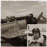
Army_Air_Force Posted March 8, 2019 Author Share Posted March 8, 2019 It's finished!!! WooHoooooo!!! Two photos from a quick photoshoot this morning. Quote Link to post Share on other sites
Chris L Posted March 8, 2019 Share Posted March 8, 2019 Very nice . Way above my ability but well worth it in the end . Cheers, Christian Quote Link to post Share on other sites
Army_Air_Force Posted March 8, 2019 Author Share Posted March 8, 2019 Thanks. I'm feeling very pleased with myself and the guy who commissioned the first model has asked for a second one. Quote Link to post Share on other sites
Army_Air_Force Posted March 8, 2019 Author Share Posted March 8, 2019 Here's a few more pictures from this morning's photoshoot. This is another model that I'll be fitting in a 3D box picture frame for wall hanging by the owner. That will be the next job as it will keep the model clean and safe. I've also got a second aircraft to build plus more casting. Quote Link to post Share on other sites
Army_Air_Force Posted March 8, 2019 Author Share Posted March 8, 2019 Another flying shot. These were done with a long M3 threaded rod screwed into one of the mounting holes in the bottom of the model. The bottom end was clamped in a vice in the garden and after the pictures were shot, the prop was blurred in photo editing. Quote Link to post Share on other sites
Army_Air_Force Posted March 8, 2019 Author Share Posted March 8, 2019 On number two, I might try cutting some white decal film for the wing and fuselage top markings. It was a fiddly masking job. Quote Link to post Share on other sites
Army_Air_Force Posted March 8, 2019 Author Share Posted March 8, 2019 Quote Link to post Share on other sites
Cubs2jets Posted March 8, 2019 Share Posted March 8, 2019 Stephen, Really nice Bush Ranger! I have really enjoyed following this thread from the beginning. It has been a great tutorial AND the end results are really nice. Thanks for sharing. C2j Quote Link to post Share on other sites
Army_Air_Force Posted March 8, 2019 Author Share Posted March 8, 2019 Cheers! It's been a challenge, but great to see serial #001 complete. It will be interesting to see what others can produce from the castings. Quote Link to post Share on other sites
Army_Air_Force Posted March 9, 2019 Author Share Posted March 9, 2019 The first four kits have now sold and are now winging their way around the world.I'd quite like a nice blue sky and white fluffy cloud background for some more flying shots of the model, but it dropped the Atlantic Ocean over home today and didn;t clear until almost dark. A sea plane would have been more appropriate!! Fingers crossed for a nice sky tomorrow. Quote Link to post Share on other sites
Army_Air_Force Posted March 13, 2019 Author Share Posted March 13, 2019 The first kits have touched down at their new airfields and I've just started the second "Bruce" build today. The background blue print picture has been glued to the backboard of the picture frame for airframe number one, and I'm just back from B&Q, having bought some thin timber for the box frame. This one should be framed up by the end of the week, between working on number two. Quote Link to post Share on other sites
Army_Air_Force Posted March 14, 2019 Author Share Posted March 14, 2019 (edited) Today I got the wood cut down to size for the box of the 3D box frame. Those parts were clamped up in a jig for the corners to be glued and 'V' nailed. It can be seen in the front part of the frame in the background of this picture. The bottom of the model had previously been drilled and tapped with two M3 holes for the mounting studs. After the studs and brass tube supports were cut to size, the model was supported by the studs on this stick, drilled with matching holes. Te stick allowed the model to be positioned over the background picture and once I was happy with the position, the stick was held still and the model carefully lifted clear. I then marked through the holes in the stick onto the background picture where it needed drilling. With the background drilled, the model wasable to be positioned for one last height check, to make sure the brass tube supports weren't holding the model higher than the depth of the frame. The model was then removed again to allow the backboard to be pilot drilled and then nailed onto the box. Edited March 14, 2019 by Army_Air_Force Quote Link to post Share on other sites

Recommended Posts
Join the conversation
You can post now and register later. If you have an account, sign in now to post with your account.