crackerjazz Posted March 2, 2019 Share Posted March 2, 2019 Hi Pete, my entry will be LLRV No. 1 (NASA 950). This LLRV initially had wheels and an open cockpit but was later modified to LLTV specs (with side controller and enclosed cockpit and pogo struts) and redesignated as LLTV A1. I'll be modelling it as such - the way it looked on the 8th of May, 1968 --- before the crash, and not after (hopefully), heheh. Quote Link to post Share on other sites
K2Pete Posted March 3, 2019 Share Posted March 3, 2019 It's good to see you here CJ! So-o-o ... you have two options ... you can complete it as LLRV #1 ... or-r-r if it doesn't get finished, as LLRV #1 AFTER the crash! Win win ... ! Pete Quote Link to post Share on other sites
crackerjazz Posted March 11, 2019 Author Share Posted March 11, 2019 (edited) Some progress shots... Edited March 11, 2019 by crackerjazz Quote Link to post Share on other sites
niart17 Posted March 11, 2019 Share Posted March 11, 2019 Such clean precise work. Blown away as always. Bill Quote Link to post Share on other sites
K2Pete Posted March 12, 2019 Share Posted March 12, 2019 4 hours ago, niart17 said: Such clean precise work. Blown away as always. Me-e-e-e ... too-o-o-o ... and to see the size of this item, beside the Tamiya glue bottle ... in all it's tiny goodness, dang cj, do you know how GOOD you are! ... oh dear, I hope I didn't jinx it now ... Pete Quote Link to post Share on other sites
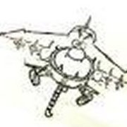
crackerjazz Posted March 12, 2019 Author Share Posted March 12, 2019 (edited) Thanks, Bill! : ) Hey, Pete, thanks! No worries, it's jinx-proof. Just the crash pieces if I don't finish, remember? : ) Even though the landing radar was updated to the box-like ones on the LLTV, this training vehicle retained the original rounded ones: Edited March 12, 2019 by crackerjazz Quote Link to post Share on other sites
niart17 Posted March 12, 2019 Share Posted March 12, 2019 I can't recall, do you have a Critcut or a Cameo Sillouette or something? I can't imagine cutting such precise clean shapes without some sort of cutter doing it. If this is old school drafting on plastic I'm super impressed even more...er. Quote Link to post Share on other sites
crackerjazz Posted March 14, 2019 Author Share Posted March 14, 2019 Hi Bill, wow, thanks! All hand-cut so far. Something I do find very useful, though, especially for parts with flat faces, is printing the part in exact size onto paper and gluing it onto sheet styrene for cutting with the xacto knife (or the Chopper by Northwest Short Line) after which I would peel the paper off. I would do this for every facet of the part then glue those flat parts together. You get more accurate cuts this way, too, than cutting pencil drawings on sheet styrene. For parts like below, though, where I can't use the technique above, I still panic and just try my best to shape something out of styrene. Quote Link to post Share on other sites
crackerjazz Posted March 16, 2019 Author Share Posted March 16, 2019 Shaped a rod into a hexagon by shaving the sides flat... I wasn't able to get any photos while building the regulators and related parts. Was too excited to see how they would look glued on. All could say is that all that cutting and gluing seemed to never end. The upper back ache it has caused hasn't let up and was so glad they're done. Unfortunately , I still have the front thrusters to do -- oh no : ( One of the pipes are too short -- will have to spin another one on the dremel. Something I noticed about using the dremel as a lathe is that the styrene rod behaves like a wagging tail. It either creates ridges on the part like what happened to the thrusters (the ridges don't show too well in the photos because the bright white color tends to wash out), or the final shape isn't really symmetrical. I've tried different blade angles to avoid it but haven't been successful so far. There has to be a way to hold down the other end. Not sure if those lathes I see online will work as they are built for wood or metal and not for flimsy 0.5mm rods. Next up will do the supports and tanks under the aft deck. Quote Link to post Share on other sites
niart17 Posted March 16, 2019 Share Posted March 16, 2019 AMAZING. Now you're making your own plastic shape hex rods?!? Comon' man' that ain't right! At least try to make it look hard so we don't feel so out-matched. Seriously though, this is really impressive. I'm learning so much. Keep it up. Bill Quote Link to post Share on other sites
CaptainObvious Posted March 16, 2019 Share Posted March 16, 2019 This is awesome work CJ! Mad skills with all that scratchbuilding. -co Quote Link to post Share on other sites
habu2 Posted March 16, 2019 Share Posted March 16, 2019 6 hours ago, crackerjazz said: Something I noticed about using the dremel as a lathe is that the styrene rod behaves like a wagging tail. .... Try slowing down your dremel. Sounds like you’re getting a vibration, a harmonic based on rod dimensions and blade pressure... Quote Link to post Share on other sites
ApolloMan Posted March 16, 2019 Share Posted March 16, 2019 I'm amazed how this is coming along, I love working with styrene. I now how easy it could work for you. I also know how it can't work for you at times, but what your doing with it, is amazing. Keep up the fantastic work mate. Quote Link to post Share on other sites
crackerjazz Posted March 19, 2019 Author Share Posted March 19, 2019 Thanks habu2, I might have to look for a speed controller. The slowest setting on mine is still way too fast. Hi Bill, CapO, ApolloMan, thanks guys! : ) Some progress on the aft deck underside. The attitude thrusters are powered by helium-pressurized Hydrogen peroxide. Got the helium tanks attached.... When the parts are too small the paper pattern glued onto the styrene sheet sometimes peels off prematurely while cutting; I find it easier to just mark where to drill and cut. Quote Link to post Share on other sites
K2Pete Posted March 19, 2019 Share Posted March 19, 2019 (edited) Ho ... Lee ... Schmitt! Your skills ... sheesh ... just out-STAND-ing! But I do love spending many minutes just looking at your build CJ ... trying to figure out just how-w-w you do-o-o it! ... meanwhile, a couple hours later-r-r ...... After perusing your build some more ... my gawd, your details are just in-cred-ible ... ( Hex nuts, really? ) your question about the wobble in the Dremel. My Dremel, even at the slowest speed, is too fast. When I tried this lathe method awhile ago, not with 0.5 mm rod, mind you, I placed the Dremel on the table top. The Rod stock was longer than it needed to be. One end of the Rod in the Dremel, the other end in a home-made block of styrene, with a little divot in it to place the free end of the rod. The block was clamped to the table top. I lathed out the middle of the Rod stock, and it was steady enough. I hope this helps CJ ... Edited March 19, 2019 by K2Pete Quote Link to post Share on other sites
crackerjazz Posted March 19, 2019 Author Share Posted March 19, 2019 Hey thanks for the tip, Pete! That helps a lot! Can't wait to try it out : ) Quote Link to post Share on other sites
as205 Posted March 19, 2019 Share Posted March 19, 2019 I just have to add to the others comments. Your work is amazing. I can't wait to see more. Quote Link to post Share on other sites
crackerjazz Posted March 28, 2019 Author Share Posted March 28, 2019 Some progress on the avionics box. Derived some measurements from a photo: Unskewed the individual panels and did a layout. Quote Link to post Share on other sites
johnlove_mk_II Posted March 28, 2019 Share Posted March 28, 2019 Very nice! Quote Link to post Share on other sites
as205 Posted April 3, 2019 Share Posted April 3, 2019 Your detail work is fantastic. The bent styrene rods look great. What method do you use to bend them without breaking them? Also, how did you do the raised rivet pattern on the side of the avionics box? Can't wait to see more! Randy Quote Link to post Share on other sites
crackerjazz Posted April 9, 2019 Author Share Posted April 9, 2019 Thanks, John! Hi Randy, thanks! The 0.3mm was very flexible and I had no issues at all bending them at 90 degrees with the long nose pliers. I do try to bend slowly to prevent breakage. The raised rivets are pin-pricks on the back of the styrene sheet, something I learned from johnbuck's fantastic LM airframe build : ) I don't know what you call this thing in the back. On LLRV No. 2 this is positioned over to the right side of the avionics box, but is in the middle on LLRV No. 1. Quote Link to post Share on other sites
ApolloMan Posted April 12, 2019 Share Posted April 12, 2019 Phenomenal. It's amazing what you can do with styrene plastic. It looks so clean and pristine. Great work Quote Link to post Share on other sites
CaptainObvious Posted April 18, 2019 Share Posted April 18, 2019 Whatever it's called, it looks great! -co Quote Link to post Share on other sites
crackerjazz Posted April 20, 2019 Author Share Posted April 20, 2019 Hey, thanks Mick and CapO!!! : ) I will now attempt to detail the engine, with the CF700 maintenance manual and Tony's photos to help me out. The CF700 engine is still in use today on the Falcon private jet so there were some good maintenance photos I found online, although the CF700 2V on the LLRV has some differences, being meant for vertical installation/operation. Some progress on the accessory drive parts... + oil tank... There's a lot to do.... about 20 years ought to do it.... Quote Link to post Share on other sites
as205 Posted April 25, 2019 Share Posted April 25, 2019 All I can say is WOW! Following this build is a real eye opener for what is possible. If on a future build I can do a quarter of what you are doing I'll be ecstatic. Quote Link to post Share on other sites

Recommended Posts
Join the conversation
You can post now and register later. If you have an account, sign in now to post with your account.