

ALF18
-
Content Count
3,823 -
Joined
-
Last visited


-
Very nice. Have you thought of doing the F-5A? Tan Model seems to have given up on that project. How much are you charging for such 3D prints? ALF
-

1-32 Tamiya Spitfire Mk IXc with Quinta Studio interior decal
ALF18 replied to ALF18's topic in In-Progress Pics
This next step is a bit tricky. The first time I glued the two side parts together (the ones shown assembled already in this step), I got them wrong. The diagram was not conclusive to me, so I ended up putting them 180 degrees out from where they should be. At that point, I had been called upstairs to mash some potatoes, a request which I never refuse if I want to stay married. The glue had time to dry on the poorly-orientated parts before I noticed it. It was only when I dry-fit one of the Y1 parts in place that I noticed it was at an angle, which is not correct. Luckily, I am using Tami -
1-32 Tamiya Spitfire Mk IXc with Quinta Studio interior decal
ALF18 replied to ALF18's topic in In-Progress Pics
Three little parts come together here. At first, the one with the funny legs sticking up gave me some trouble, because I was fitting it in place backward. I was trying to fit the side of that part that is facing out of the page in the instructions onto the face of part H40. I tried a few times, but it didn't locate right. Flipping it around, it instantly fit perfectly in place - just like everything else Tamiya engineers. -
1-32 Tamiya Spitfire Mk IXc with Quinta Studio interior decal
ALF18 replied to ALF18's topic in In-Progress Pics
This next part was tricky. Two little silicone tubes slide into depressions in the back part, and a little nut goes into the part that glues on top of it. Easy to figure out which of the silicone parts were intended - the others are significantly larger. Less obvious was which of the nuts (the larger of the two silver ones, or the black one) was to fit into the other part. Holding them up to the full-scale drawing in the instructions, it was hard to tell while they were still in the bag. I am too afraid of the carpet monster to pull them all out and risk losing them in the process. Flipp -
1-32 Tamiya Spitfire Mk IXc with Quinta Studio interior decal
ALF18 replied to ALF18's topic in In-Progress Pics
One fun thing about the engine is it also teaches me how the big V-12 works. Note how well the row of six cylinders fits onto the crankcase here. The moulded detail is incredible, and the parts fit beautifully together. Given that these parts would be largely painted black, that little seam will be invisible. The intercooler pump is tiny, but made of three parts. Careful study of the drawings is necessary to make sure things go together in the correct orientation. There are some PE parts here - CA glue does the job. In the pics, I can see that the PE has an upper and lower side (with -
1-32 Tamiya Spitfire Mk IXc with Quinta Studio interior decal
ALF18 replied to ALF18's topic in In-Progress Pics
In parallel to the engine, I built up the main landing gear legs and their doors. What's easy is that the colour is 'underside,' meaning I can paint everything at once on these. The oleos are silver, so I'll use my silver pen to add that detail after the big bits are painted. All these parts go together beautifully. I've also prepped the wheel parts. I'll be using the rubber tires (or should I say tyres, given it's a British aircraft?). So confusing. 🤥 You can see the glossy silver from my pen on some of the parts. Still have to figure out exactly how the PE parts fit into the whole -
1-32 Tamiya Spitfire Mk IXc with Quinta Studio interior decal
ALF18 replied to ALF18's topic in In-Progress Pics
Thanks, Barkin Mad, for your confirmation of the flaps and radiator configurations. Easier to build this way as well. 😏 Progress has been in fits and starts, due partly to the fact I've been teaching online Aviation English and Supersonic/Transsonic Theory of Flight courses at the Aviation College I taught at full time until five years ago. Due to the shortage of pilots in the industry, they finally bent on the 'never online' approach they had, and I'm able to do classes from home. While it's good money, and fun to once again interact with enthusiastic professional pilot trainees, it has -
Interesting information, Kursada. Janissary, that is one awesome build. Looks fantastic. As promised in a DM, here is what I found for RHAWR (Canadians called it the radar homing and warning receiver at the time, not RWR). A user here on ARC, called CF-104 of course, made a great version of a CF-104 that will show you how he did it. He knows a lot about the real aircraft, and I learned some stuff from him as well. For your interest, I dug up some photos I took in a museum at Edmonton Municipal Airport almost 10 years ago. The Starfighter they have on display is called a CF-1
-
Thanks, Scooby! Great memories from Baden, back in the day. ALF
-
So, Bekim... are the 3D prints made out of solid gold? I suspect the prices will be high enough to expect them to be made of gold. 😏 ALF
-
Here's the pod, on a CF-104 that was involved in a Tactical Air Meet in 1974. Illu is correct, the CF-104 doesn't have a suffix, but the tail makes it look like a G. Differences include (CF-104 doesn't have): IR sensor at bottom of windscreen, bulged main gear doors, beefy main landing gear wheels.
-
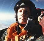
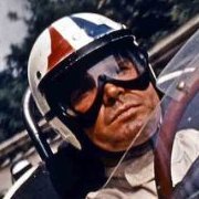
Super work! I especially love the authentic-looking paint job. 😍🏆 Here's what CF-104s looked like back in 1974, when my father flew them. This aircraft took part in the Tactical Weapons Meet. I was 15 years old, and used to climb under the barbed wire by the control tower in Baden to watch the jets taxi by. The Military Police never caught us, and the pilots all waved at us as they went by. The second picture is at a Tiger Meet, with my father at far right in the photo. Fantastic job, Janissary!
-
1-32 Tamiya Spitfire Mk IXc with Quinta Studio interior decal
ALF18 replied to ALF18's topic in In-Progress Pics
Horizontal stabilizers and elevators installed. Tiny, fiddly parts for the hinges. I'm about to work on the radiators. Not sure if they should have open or closed fairings. Anyone know? I plan to have the flaps up, since I've learned from several reliable sources that Spits almost always got parked with flaps up, despite the kit having the flaps down option and lots of after-market stuff is made for this state. Fairings... looking into it. In the meantime, here is the finished upper and lower wing. It all fits very nicely. -
1-32 Tamiya Spitfire Mk IXc with Quinta Studio interior decal
ALF18 replied to ALF18's topic in In-Progress Pics
The bays are in place, and the long part along the top also fits perfectly in front of them. Now, the wing halves. They went together nicely as well, with no gaps. More soon. ALF -
1-32 Tamiya Spitfire Mk IXc with Quinta Studio interior decal
ALF18 replied to ALF18's topic in In-Progress Pics
Main landing gear. Parts L and R (the outer parts of the MLG bays) have about 6 parts each, which took a while to put together. Again, all fit nicely into place. The other L and R, the parts that cover the MLG struts, were interesting in themselves. There is reference to SB7, a 1.6 mm nut. Again, flipping to the back, I found drawings and references to the parts. Nuts and bolts are in a little plastic bag. There are four total nuts, one each 2.6 and 2 mm, and two 1.6 mm ones. I carefully fished out the tiniest ones, and saw that it fits the full-size drawing in this step of the inst