as205 Posted March 21, 2023 Author Share Posted March 21, 2023 Pete: Thanks. The NewWare enhancements helped a lot. The additional brass parts on the SM and the High Gain dishes came from them. But all in all, the SM is much easier to make look good than the LM. I forgot to mention in the update that the SM had to be painted twice. I was removing the masking on the white areas and noticed that I was rubbing off the Alclad Stainless Steel paint. I had to re-mask and re-paint it and then applied Alclad clear coat over that. That worked, plus I was much more careful in my handling the second time around. Southwestforests: Oh yes, I'm well aware of the CA/clear styrene interactions. That is why I used Plasti-Zap. I've used it on several occasions before with absolutely no problems. It didn't occur to me that it might interact with Kristal Klear. Lesson learned on that one! For the beauty shots, I decided I'd shoot on a black background and then edit out the rod holding it up. They turned out OK. Quote Link to post Share on other sites
as205 Posted April 13, 2023 Author Share Posted April 13, 2023 I got a little more work done on the LM. I finally decided what I was going to do with the folded landing gear. I took the deployed gear parts and cut them at the hinge line. I then did some mild shaping at the joint and glued the two sections together in a folded orientation. I then applied some putty at the joint to smooth things out a bit. The picture shows the spliced gear and the folded gear from the kit. It’s not perfect and the angles are of course off but I guess it’s passable. The bottom of the Descent Stage is not correct or the kit gear is too small but whatever the case it causes the folded gear into a raised angle when it should be nearly flat. But I’m really done fighting with it so I’m willing to accept it in this state. I then moved back to the Descent Stage main body. I’ve finally decided to do this model as Apollo 10. The LM on Apollo 10 did not have the plume deflectors. Those were added starting with Apollo 11. I needed to use the small rectangular pieces that are not called out in the instructions to fill the open holes in the sides of the Descent Stage. They don’t fit very well, and the crinkle pattern is not a good match for the rest of the stage. Here are a couple of pictures showing how well they fit. 🤣 They are too tall and not quite wide enough for the holes. Here is a view from a different quadrant. Mr. Surfacer 500 Putty was liberally applied in several layers to better blend them in. I also trimmed off the excess that is raised above the top of the Descent Stage. Mr. Surfacer 500 applied roughly does a good job disguising the parts. Here is a view from the top. Since I’m not using the pre-folded gear parts I needed to fill in the massive holes in the bottom of the Descent Stage. Once I had all the holes filled I gave the Descent Stage a coat of primer to verify that I had all the imperfections covered. Here is the bottom with primer. Now it’s time to start applying some paint and foil. Before I get too far along with that though I’ll have to get the landing gear modified. Look for that in the next update. Thanks for looking. Quote Link to post Share on other sites
K2Pete Posted April 15, 2023 Share Posted April 15, 2023 It's looking good Randy ... but you just may be sweating the details. Those Plume Deflector plugs just needed a little filing and right now we can't tell there was a patch there ... so ... nice job! The Landing Gear, again, we'll be distracted by the shiny foil and details on the Ascent Stage, like antennae, RCS etc. In my experience, details like downlocks, ladder rungs, landing probes are missed by even the Eagle eyed Judges, as well as casual viewers. Just 'weenies' like me would notice, but again, I go for the major look of the subject ... those details, um-m-m ... not so much. But, like you, I KNOW they're there ... so I really do understand where you're coming from! Just don't get too discouraged by the folded Landing Gear ... they'll be tucked under the Descent Stage and we'll be dazzled, nay OVERwhelmed, by the CSM ... ;^ D)) ... "oh, did you see the LM?" "What? ... you mean there was a LM too??" Pete Quote Link to post Share on other sites
crackerjazz Posted April 15, 2023 Share Posted April 15, 2023 Hi Randy, I just saw this thread. Some cool stuff going on here! : ) Following along : ) Quote Link to post Share on other sites
kellyF15 Posted April 22, 2023 Share Posted April 22, 2023 This build is looking awesome! Quote Link to post Share on other sites
as205 Posted April 23, 2023 Author Share Posted April 23, 2023 Thanks for that. It's been slow going lately, lots of outside stuff distracting me. Quote Link to post Share on other sites
as205 Posted August 21, 2023 Author Share Posted August 21, 2023 After a long layoff I’ve finally gotten back to the Apollo 10 build. I’ve had a bunch of other things on my plate lately and, to be honest, I just haven’t gotten my modeling mojo back. But, I felt like if I don’t get back and try to restart the project it will never get finished. So, I got back to work on the landing gear for the LM. I finished folding the gear sections and did a bit of trimming and applying putty. Then they got a coat of primer. They aren’t exactly scale, but they do look better than the pre-folded part provided in the kit. I finished the legs by sanding off the molded in foil on the lower section of the leg since Apollo 10 didn’t have any. I also cleaned up the ladder which had quite a bit of flash/off register mold lines. I also sprayed them with primer. The landing pads were a bit of a booger to prep. I needed to remove all the molded in foil since Apollo 10 didn’t have any foil applied to the landing pads (except for a tiny bit on the quarter that faced the rocket nozzle). The bottoms were not too hard to do, but the top surface was tricky. I first tried sanding, but given their size that wasn’t working out too well. I ended up applying some Mr. Putty 500 to the surface to somewhat level out the crinkles. I then took a Dremel tool with a carving bit and went around the inside. This worked fairly well. You can see a bit of unevenness around the edges that I’ll have to clean up but I think this will do the trick. I was looking over the Ascent Stage main body and noticed a couple of areas that I’ll need to fill and I also noted that I had forgotten to add one of the New-Ware resin parts above the right hand propellant tank. I glued that on and applied a coat of primer. That showed up some areas that I need to clean up and then re-prime. That’s it for now. I’m about ready to apply a gloss black base coat to the Descent Stage and start the detail painting, but I’m going to have to wait for this heat wave to pass. The garage is so warm that the paint would almost certainly dry before it hit the surface. It’s been over 100 every day this week with very high humidity, so no painting until it can cool off a bit. Quote Link to post Share on other sites
janman Posted August 28, 2023 Share Posted August 28, 2023 Great work! I only now found this thread but will be following closely. It will be interesting to see your solutions. I've been toying with idea of building one myself for years now. I was thrilled when I found out there was a new 1/72 kit available, especially of the LM. But given the facts that these seem to rather rare and hard to get plus you'll have to pay a hefty price for them I've still not acquired any of these kits. I'm also aware they are far from perfect and your project further underlines this. My original vision was to show a finished LM with 1/72 Tomcat - Grumman products as they are - and combine two of my great points of interests. Who knows, maybe I'll pick up one when the opportunity rises. Meanwhile I'll probably dig up my Tom Kelly Lunar Lander book. 🙂 Quote Link to post Share on other sites
as205 Posted September 12, 2023 Author Share Posted September 12, 2023 A little more work got done on the Dragon model in the last few days. I started with the steerable S-band antenna. Looking at my reference photos I noticed that the main post for the antenna projected more from the side of LM and not the top. The Dragon parts are made for a top mount. So I filled the hole in the top of the LM with putty and allowed it to dry. The New-Ware replacement parts for the steerable S-band can be seen in the below photo, which also shows the filled mounting hole. The replacement parts are much more accurate. The Dragon part for the antenna support is just barely in above picture on the right. I will lengthen the main support post so it will fit into a new hole that I will drill into the side of the LM. I moved over to the descent stage and sprayed it black and gave it a matte overcoat. I then started the process of adding the details to it. It will be a combination of paint and Bare-Metal foil. The first area to get the bright aluminum foil was the top center. There is more to do with the top but since I had the bright aluminum out I did the bottom of the descent stage. Apollo 10 had a very unique pattern. Thanks to the Paul Fjeld website and Mike Mackowski’s SIM 7.1 for the marking guides for Apollo 10. There is more to do. I also have some Bare-Metal Gold foil that will be used. I will also be painting some of the Bare-Metal foil with Tamiya transparent yellow, orange, and red to get the shades I need. Next, I worked on some of the detail parts on the LM. Beginning with the VHF antennas. I painted the antennas black and white as they were seen in photos. I then foiled the supports with Bare-Metal foil. I did use some Micro Scale Foil Adhesive to provide a bit of extra ‘stick’ since the foil is a bit on the old side. Next up was the steerable S-band antenna. After assembling the antenna array, I painted the front side flat white and the back side flat black. I did this after careful examination of my LM photos. The antenna support had previously been lengthened for the new mounting point on the LM. I then foiled it in a similar manner as I did with the VHF antennas. I then started on the rendezvous radar. The dish was not well done. I used my Dremel and removed the very large feed horn in the center of the dish. I then used a small drill and put in four small depressions where the reflector assembly would go. Since I used the New-Ware S-band antenna I was able to cut the feed horn from the Dragon S-band and glue it into the rendezvous radar dish. For the reflector I used four small styrene rods put together with Tenax. I will not glue that in until after the assembly is attached to the LM. Here is a photo of the modified part. Next up were some more detail parts. The docking target came from the New-Ware detail set. It was primed and then painted flat white. I then carefully painted the black areas with flat black with a small brush and a small amount of paint. My fingers are not what they used to be so to do the black, I placed the two parts on the edge of some masking tape to keep them in place and then, under my magnifier, painted them with a very small brush. On the left of the picture is the New-Ware resin EVA antenna in stowed position. At the top is the landing radar. It was painted with Alclad II chrome over gloss black base. The item next to it is the New-Ware photo-etch landing radar shield. Lots more to do, but that’s it for now. Quote Link to post Share on other sites
MajorJim Posted September 24, 2023 Share Posted September 24, 2023 I’m really enjoying seeing this come together. Quote Link to post Share on other sites
as205 Posted October 5, 2023 Author Share Posted October 5, 2023 Most of my outside distractions are disappearing, so the delays can now pretty much be blamed on procrastination. However, progress has been made. I've been working on the Descent Stage of Snoopy. The landing radar is installed. It almost disappears in the shine of the foiled underside. I've applied the foil details on the top and sides of the Descent stage. I used four colors of foil. Bare-metal foil Bright Aluminum, Gold, Yellow Gold, and Dark Orange. The Aluminum and Gold are the bare colors of the foil. The Yellow Gold is the Bright Aluminum painted with a couple of coats of Tamiya Transparent Yellow. The Dark Orange is the Gold foil painted with three coats of Tamiya Transparent Orange and one coat of Tamiya Transparent Red. I think they came out OK. I applied the two decals to the Yellow Gold rectangles. It gives the appearance of having a Yellow Gold border around the decals. Here is a view of all four sides. I painted the primary struts with Alclad Chrome. Then I painted the section with no molded kapton with Tamiya Metalic Gray. The ladder was painted Tamiya Flat Aluminum. The folded secondary struts are painted with Alclad Chrome. Then the large diameter sections were painted Tamiya Flat Gray. The tops of some of the braces were painted Vallejo Black. The two on the left are showing the top side of the braces and the right two show the bottom. The landing pads were painted Tamiya Flat Gray. The lower outriggers were painted with Alclad Chrome and then covered with a couple of coats of Tamiya Transparent Orange. The nozzle is painted with two shades of gray. The porch is painted with a custom mix to get a shade of tan that I'm happy with. I next used CA to glue the lower outriggers to the Descent Stage body and upper outrigger. When those cured I used CA to attach the landing radar heat shield and then the Descent Stage engine nozzle. While that was curing I attached the primary struts to the landing pads. Once those were cured I again used CA to attach the primary struts to the outriggers and secondary struts. Here are a couple of photos of the completed Descent Stage. I have a few minor paint touch ups to do, but it is completely assembled. That's it for now. It's time to get the parts all together and move on the the Ascent Stage. Quote Link to post Share on other sites
K2Pete Posted October 6, 2023 Share Posted October 6, 2023 Looking at your LM, I'm gettin' the urge to build another one, but without foil ... to leave all the mods, the putty, the added styrene, the PE and Resin bits visible. I just like the look of it. ;^ D Forecasts are that Winter's gonna be a c-c-cold one! Perfect for sitting and building a scale model ;^ ) Did you find many ref pix for this Apollo 10 LM, Randy? All I could find for mine, was just a few on Apollo Archive ... but I'm also curious about your copper colour on the top side of the Descent Stage. Still watchin'! Pete Quote Link to post Share on other sites
as205 Posted October 7, 2023 Author Share Posted October 7, 2023 Thanks Pete. Like yourself I've found very few photos of Snoopy. I'm mostly going from Mike Mackowski's SIM 7.1 LM book. The copper color on the top side of the Descent Stage is Bare-Metal Foil Bright Aluminum with three coats of Tamiya transparent orange and one coat of Tamiya transparent red. It came fairly close to the color in some of the photos of the LM topside. Randy Quote Link to post Share on other sites
K2Pete Posted October 7, 2023 Share Posted October 7, 2023 Here's a site from Paul Fjeld ( F-yell). He used to be with the Cradle of Aviation in New Jersey IIRC, and rebuilt LM-13. He was also heavily involved in rebuilding the LM at the Smithsonian. Take a peek at this site, on page 2 is Snoopy's patterns as well as the others. https://pfinspace.com/lmdata/ Pete Quote Link to post Share on other sites
as205 Posted October 7, 2023 Author Share Posted October 7, 2023 Pete, Thanks, I have those as well. Lacking any definitive photos, I picked a path and executed. I took a while going over those and you really can't go wrong either way since we don't have the photos (at least I can't find any) to give guidance. Randy Quote Link to post Share on other sites
SpacecraftGuy Posted October 7, 2023 Share Posted October 7, 2023 Lovely, intricate work! The only pre-flight photo I have of Snoopy doesn't show the topside of the descent stage. But just in case you haven't seen this one... Quote Link to post Share on other sites
as205 Posted October 8, 2023 Author Share Posted October 8, 2023 SpacecraftGuy, Thanks. Yes I have that one, plus a couple of others. But the main problem with them is that at the time of the photo not all of the coverings were on the LM so it is difficult gauge what is correct when it was actually launched. Paul Fjeld and Mike Mackowski have some drawings that I'm accepting as close enough. BTW, I did make some progress today with the Ascent Stage. It got its aluminum base coat. Randy Quote Link to post Share on other sites
as205 Posted October 13, 2023 Author Share Posted October 13, 2023 Having pretty much wrapped up the Descent Stage, I started work on the Ascent Stage. I started painting with the mid and aft section of the LM. I painted it Model Master Acryl Aluminum. I then painted the panels that were black with Vallejo Model Color Black. When that had dried I went back and scraped the paint off where the panels met. Next, I covered the black areas with some Vallejo Matt Varnish to protect the paint. LM-4 was the last LM to have the overall Aluminum finish. All later flights had one type or another of anodizing. Then I started applying foil where it was needed. The below photo shows the bottom of the stage. Later flights had gold/orange kapton applied here. I tried to get some wrinkles in the foil but I didn’t get as many wrinkles as I would have liked. The lower half of the RCS quads were also covered in wrinkled foil. You can see that I’ve glued in the Ascent Stage engine nozzle. The inside is not painted since it will not be seen when the model is finished. Below is a photo of the left side. I painted the interior black since I was not doing an interior and the front and rendezvous windows would allow viewing of the bare interior. The left side had a small area that needed some details. I used gold and dark orange foil sections and one small rectangular area was painted Tamiya Japanese Navy Gray, which has a slight greenish gray tint. That just about finishes this sub assembly. This section has a lot of small antennas that will be added after the front section is glued on. Next, I started on the front section. First I applied some gold foil to the frame of the front hatch. The two semi-circular sections were then given three coats of Tamiya Transparent Orange. Next I attached the rendezvous radar and painted the supports Vallejo Black. Note the beacon light. It is a New-Ware photoetched part and the outside circular area was painted Vallejo White. I then pooled some Vallejo Clear Varnish in the center to somewhat model the glass light bulb that was there. The below photo shows the completed dish section of the rendezvous radar. The rendezvous radar pointed aft when stowed. There is more black to be applied plus some foil around the RCS quads and the front hatch. When I complete that I’ll install the photoetch handrail that leads up to the top of the LM. The inside areas that may be visible through the windows were also painted black. That’s it for now. Still a bunch of small stuff to complete, but the finish line is in sight. Quote Link to post Share on other sites
K2Pete Posted October 14, 2023 Share Posted October 14, 2023 (edited) WHAT?? You framed the front hatch with foil?? ... Holy Kow ... you've got good eyes and steady hands young man! Nicely Done Randy ... do you have decals for this itsy-bitsy LM? If yes, are they kit or Rick Sternbach? Keep 'er goin' Randy! ;^ D Pete OOOPS ... yes you've already applied decals to the Descent Stage ... so nevermind Randy! ;^ ) Edited October 14, 2023 by K2Pete typo ;^ ) and correction Quote Link to post Share on other sites
as205 Posted October 14, 2023 Author Share Posted October 14, 2023 Thanks Pete, I used a fresh #11 blade and took a few deep breaths and went after it. Outside edge first, then pealed the excess off. Then took another few breaths and went after the inside. I just finished adding the foil to the sides of the porch. It came out pretty good. No photos yet, but they are to come. Randy Quote Link to post Share on other sites
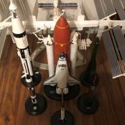
as205 Posted November 2, 2023 Author Share Posted November 2, 2023 Work on the Ascent stage continued with more foil work. Before I added the foil, I painted some black on the lower cabin and the RCS quads. Foil was then added around the hatch area, the area below and under the “gills” and the lower sections of the front RCS quads. Next I painted the black areas around and below the windows. The notch in the black near the hatch was painted light gray. Then I painted the sides of the “nose” and part of the “gills”. I cut some clear 0.010 styrene to fit the window openings. This was glued in with Plasti-Zap CA glue. There were a couple of small gaps that I filled with Mr. Putty 500. Then the inside black paint was touched up. I used the Space Model Systems decals for the windows and hatch. The window decals were applied on the inside of the windows. If you apply the decals to the outside the text will be backwards. (Assuming that you can read the text at this scale.) Here are a couple of photos. Note that I also added the EVA handrail. From my photo research it appears that the New-Ware EVA handrail photoetch part is about a quarter of an inch too short. Rather than try to scratch one with styrene I went with the photoetch part. That completed the front of the LM. I glued it to the rest of the Ascent stage with some Tenax. The Ascent stage was now ready for the remaining details. This view shows the front left side of the Ascent stage. I painted the RCS nozzles with some Alclad Burnt Metal and attached them with CA. I could now add the kit supplied strut that runs from the bottom front to the fuel tank. Visible also is one of the VHF antennas and the docking target. The below photo shows the rear left side. You can see the docking target better from this angle. The top and bottom of the target were photoetch from the New-Ware set. The pole is from the kit with the top cut off. The kit part was too tall so it was shortened. I glued a small strip of 0.010 styrene to the underside of the “T” bar to make it easier to securely attach it to the pole. You can also see that I added a bit of Vallejo Iraqi Sand to the bump on the back of the Ascent stage. I have no idea what that bump is, I’ve searched all my docs and can’t find where it is identified. I’m not sure that LM-4 had an EVA antenna, but I can’t find any photo evidence that it didn’t. I did notice that LM-3 didn’t have one, but nothing definitive for LM-4. Here is a photo of the right side showing the steerable S-Band antenna. By the way, after all these photos were done, I noticed that I had not painted the black panels on the back of the midsection. With the VHF antenna installed, it will be a bugger to fix but I’ll give it a try. I glued the Ascent and Descent stages together with a small amount of 5-minute epoxy. The stages fit together well and I could probably have not used any glue, but I didn’t want to risk it. Here is a series of photos around the completed LM. It starts with the front view. The the left side. Here is the back side. Note the upper panels are painted now. Finally the right side. I also did a couple of shots from above. Below is a series of photos of the completed model. I shot them in front of a black background and edited out rod that holds them up. That completes this build. It’s been a year long, good grief. I like the end result. I used some skills that I haven’t used in quite some time so that was fun. The kit itself produced some frustrations but I think they were all dealt with sufficiently well. If I had been thinking further ahead I would have drilled the mounting hole in the Service Module closer to the CM heatshield so that the combined CSM/LM would be a bit more balanced. That LM is quite the chunk of plastic for it’s size. I intend to mount this on a wood plate along with the Horizon 1/72 Mercury and the 1/72 Dragon Gemini kits. That will show the U.S. 1960’s manned spacecraft in one place at the same scale. I’ll post a photo of the combined kits when I get that done. Thanks for looking. Quote Link to post Share on other sites
K2Pete Posted November 2, 2023 Share Posted November 2, 2023 Nicely Done Randy! I would doubt the EVA antenna was attached ... for the same reason the landing probes weren't, they weren't needed. But, hey, I can't confirm it either. That antenna may have been used so John Young could hear Cernan's blue language later on ... ;^ D And that little bump on the aft panels, I thought I knew what it was but can't find it. I thought it might be in Virtual LM, but not at a quick glance. Those painted upper aft panels look great! You've got a nice steady hand young man! And your pix are terrific! This little model really looks good! And I hafta tell ya, I never get tired of seeing these 1960's Space vehicles. Such a remarkable feat of engineering! Thanx Randy! Pete Quote Link to post Share on other sites
Ricardo Salamé Posted November 9, 2023 Share Posted November 9, 2023 These may solve your puzzle Pete Regards Quote Link to post Share on other sites
Ricardo Salamé Posted November 9, 2023 Share Posted November 9, 2023 On 10/24/2023 at 8:32 PM, LA2019 said: Yeah, the astronaut is a small guy! I glued him down to the head of a thumb tack just so I wouldn't lose him. 5 minutes ago, Ricardo Salamé said: Nice touch this fellow. It give you the sense of scale Ricardo On 11/2/2023 at 5:59 AM, K2Pete said: Nicely Done Randy! I would doubt the EVA antenna was attached ... for the same reason the landing probes weren't, they weren't needed. But, hey, I can't confirm it either. That antenna may have been used so John Young could hear Cernan's blue language later on ... ;^ D And that little bump on the aft panels, I thought I knew what it was but can't find it. I thought it might be in Virtual LM, but not at a quick glance. Those painted upper aft panels look great! You've got a nice steady hand young man! And your pix are terrific! This little model really looks good! And I hafta tell ya, I never get tired of seeing these 1960's Space vehicles. Such a remarkable feat of engineering! Thanx Randy! Pete On 11/1/2023 at 11:42 PM, as205 said: Work on the Ascent stage continued with more foil work. Before I added the foil, I painted some black on the lower cabin and the RCS quads. Foil was then added around the hatch area, the area below and under the “gills” and the lower sections of the front RCS quads. Next I painted the black areas around and below the windows. The notch in the black near the hatch was painted light gray. Then I painted the sides of the “nose” and part of the “gills”. I cut some clear 0.010 styrene to fit the window openings. This was glued in with Plasti-Zap CA glue. There were a couple of small gaps that I filled with Mr. Putty 500. Then the inside black paint was touched up. I used the Space Model Systems decals for the windows and hatch. The window decals were applied on the inside of the windows. If you apply the decals to the outside the text will be backwards. (Assuming that you can read the text at this scale.) Here are a couple of photos. Note that I also added the EVA handrail. From my photo research it appears that the New-Ware EVA handrail photoetch part is about a quarter of an inch too short. Rather than try to scratch one with styrene I went with the photoetch part. That completed the front of the LM. I glued it to the rest of the Ascent stage with some Tenax. The Ascent stage was now ready for the remaining details. This view shows the front left side of the Ascent stage. I painted the RCS nozzles with some Alclad Burnt Metal and attached them with CA. I could now add the kit supplied strut that runs from the bottom front to the fuel tank. Visible also is one of the VHF antennas and the docking target. The below photo shows the rear left side. You can see the docking target better from this angle. The top and bottom of the target were photoetch from the New-Ware set. The pole is from the kit with the top cut off. The kit part was too tall so it was shortened. I glued a small strip of 0.010 styrene to the underside of the “T” bar to make it easier to securely attach it to the pole. You can also see that I added a bit of Vallejo Iraqi Sand to the bump on the back of the Ascent stage. I have no idea what that bump is, I’ve searched all my docs and can’t find where it is identified. I’m not sure that LM-4 had an EVA antenna, but I can’t find any photo evidence that it didn’t. I did notice that LM-3 didn’t have one, but nothing definitive for LM-4. Here is a photo of the right side showing the steerable S-Band antenna. By the way, after all these photos were done, I noticed that I had not painted the black panels on the back of the midsection. With the VHF antenna installed, it will be a bugger to fix but I’ll give it a try. I glued the Ascent and Descent stages together with a small amount of 5-minute epoxy. The stages fit together well and I could probably have not used any glue, but I didn’t want to risk it. Here is a series of photos around the completed LM. It starts with the front view. The the left side. Here is the back side. Note the upper panels are painted now. Finally the right side. I also did a couple of shots from above. Below is a series of photos of the completed model. I shot them in front of a black background and edited out rod that holds them up. That completes this build. It’s been a year long, good grief. I like the end result. I used some skills that I haven’t used in quite some time so that was fun. The kit itself produced some frustrations but I think they were all dealt with sufficiently well. If I had been thinking further ahead I would have drilled the mounting hole in the Service Module closer to the CM heatshield so that the combined CSM/LM would be a bit more balanced. That LM is quite the chunk of plastic for it’s size. I intend to mount this on a wood plate along with the Horizon 1/72 Mercury and the 1/72 Dragon Gemini kits. That will show the U.S. 1960’s manned spacecraft in one place at the same scale. I’ll post a photo of the combined kits when I get that done. Thanks for looking. Nicely done Randy!!! Apollo 10 it's like a forgotten subject. You capture it right Regards Ricardo Quote Link to post Share on other sites
as205 Posted November 11, 2023 Author Share Posted November 11, 2023 Thanks Pete and Ricardo. One day I hope do one on par with yours. Randy Quote Link to post Share on other sites

Recommended Posts
Join the conversation
You can post now and register later. If you have an account, sign in now to post with your account.