spaceman Posted October 24, 2022 Share Posted October 24, 2022 The Lord of 3D Prints has done conjuring tricks again, you are the purest sorcerer, Joe, I congratulate and freeze in awe. Quote Link to post Share on other sites
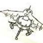
crackerjazz Posted October 24, 2022 Author Share Posted October 24, 2022 (edited) Hi Spacecraftguy, Spaceman, thanks! : ) 1/24 engine aft section parts after support cleanup and curing. Had to be very careful with the support removal on the blades which were very thin -- you cut the supports and they push up on the blades. I did manage to break a couple blades and had to replace them with carved up sprue (er, supports, rather : ). This is deja vu.. I remember doing this in styrene : ) Edited October 24, 2022 by crackerjazz Quote Link to post Share on other sites
spaceman Posted October 24, 2022 Share Posted October 24, 2022 Hey Joe, too bad you didn't take a shot of the 1.000 supports on the blades. All the parts look fantastic. Quote Link to post Share on other sites
K2Pete Posted October 24, 2022 Share Posted October 24, 2022 This visual treat, this Eye-Candy, is difficult to believe CJ. The investment in time that these parts represent amazes me. Learning the ins and outs of the software to achieve these highly detailed, highly accurate and stunning, I mean, STUNNING parts. Then there's the acquired skill of the process of the 'after-print' removal of supports and curing. Not to mention the care of realizing the turbine blades need to be corrected. I'm blown away CJ ... then there's the prints themselves. The details that this tech provides ... all I can say is "WOW"! Thanx for sharing all this with us Joe! ;- D ... and keep up the lovely work! Pete Quote Link to post Share on other sites
mhvink Posted October 24, 2022 Share Posted October 24, 2022 So, what kind of fuel will this thing use when you get it finished? Awesome work!! Mike Quote Link to post Share on other sites
crackerjazz Posted October 25, 2022 Author Share Posted October 25, 2022 (edited) Hi mhvink, thanks! : ) Thanks, Pete : ) Technology sure has helped move this project along in ways I never imagined. Hopefully I can get it done by 2024 for the LLRV's first flight anniversary : ) That's a nice round goal - 10 years for building and in time for the 60th anniversary : ) Ten years -- wow, that's a big chunk of my life, lol. You know, everyday I gently run my hands on the printer's cover and tell her not to break down on me : ) Hi Manfred thanks -- I did take a photo but I figured you guys were tired of seeing prints with supports on the build plate : ) You can't see it too well, but I put two supports per blade -- one at the end and one near the middle. That's probably the reason they easily broke when cutting the supports as they had no flex to them that way. I should really be trying out the ABS-like resin but I'm worried about the fumes as my mancave doesn't have adequate ventilation. I wanted to practice some more so I printed a few more fans in the hopes of coming up with one without any broken blades. And this time I just put a single support at the end of the blade. At first I tried using a my regular cutting pliers and cut at the very tip of the support but they still pushed the end of the blade upwards and the cuts weren't so clean. There's a type of cutter that shears instead of compresses and that should help cut the supports without pushing them apart but the ones I have are too big. I tried a different method this time -- cutting with the xacto near the base of the support and just pulling them out with the tweezers and that worked really well. I don't have to be this careful, really, on the supports on the other areas of the fan. I normally just cut away and twist them off -- it's only these fragile blades that require a little patience. I think I got the technique down. It doesn't take too long to do. I actually timed myself and I could do one fan in under 6 minutes. And I now have 4 fans with zero broken blades. Man, what we do for our models -- no wonder our wives think we care more about our models than them. The love and patience we shower these things with -- somehow, they're right, aren't they : ) Edited October 25, 2022 by crackerjazz Quote Link to post Share on other sites
niart17 Posted October 25, 2022 Share Posted October 25, 2022 Incredible work! Your prints are turning out perfect. i made some blades kind of similar to those for my Millennium Falcon model and had the same issue. What I finally ended up doing was using a thin cutting wheel in a rotary tool and cutting the supports at the raft at a slow speed and then breaking off like you did. Might be a bit faster for ya one the next one. I'm just blown away by this project. Bill Quote Link to post Share on other sites
CaptKirk Posted October 25, 2022 Share Posted October 25, 2022 Beautiful, beautiful work. Quote Link to post Share on other sites
crackerjazz Posted October 26, 2022 Author Share Posted October 26, 2022 (edited) Thanks, Bill and CaptKirk! : ) I was trying to recall where the fans are on the Falcon's engine and just remembered -- the engine deck : ) That's a cool technique using the rotary tool, thanks! I'm also thinking about how far a fan blade can extend outwards without supports. Once the first layer of blade prints on the FEP, the body can still peel it off the FEP from one side. The blade extends outward less than 4mm so maybe it can do without them? Will risk a failed print and see : ) The worst thing that can happen is I'll be peeling off little lines of blade from the FEP -- that can be a pain. But we won't know if we don't try so I'll just go ahead and give it a whirl. Edited October 26, 2022 by crackerjazz Quote Link to post Share on other sites
crackerjazz Posted October 26, 2022 Author Share Posted October 26, 2022 Wow, will you lookee that : 0 I was actually mentally prepared to start scraping off blades from the FEP when the printer beeped "done". But when I peeked up at the build plate the fans were fully grown and smiling at me. I'm tempted to delete the photos showing me pulling off all those blade supports but it'll be fun to look back on. It did help that the blades didn't have any "islands" and the lowest layer was fully connected to the body but I'm surpised that at that length and being that thin, they didn't need supports and can be pulled off the FEP from only one end without breaking. Maybe they don't stick to the FEP all that much when the surface area is minimal? This is like magic to me : ) Quote Link to post Share on other sites
spaceman Posted October 26, 2022 Share Posted October 26, 2022 (edited) I fully agree with you, Joe, it's really a kind of magic, simply perfect! And you keep getting better, step by step. Keep it up! Nothing ventured, nothing gained. Edited October 26, 2022 by spaceman Quote Link to post Share on other sites
niart17 Posted October 27, 2022 Share Posted October 27, 2022 WOW! That should NOT work. Ya' must have some kind of voodoo working for ya. If I'd tried that I'd likely end up having to change the FEP for sure. Good job! Quote Link to post Share on other sites
habu2 Posted October 31, 2022 Share Posted October 31, 2022 (edited) On 10/25/2022 at 6:55 AM, crackerjazz said: Technology sure has helped move this project along in ways I never imagined. Looking at your excellent work, I can't help but wonder what those Bell engineers who designed the LLRV, armed only with their slide rules, T-squares and mechanical pencils some six decades ago would think of this technology, and the ability to do CAD design and 3D printing. Boggles the mind... I remember sitting at a drafting table back in the 70s, drawing isometrics, projections, surface revolutions etc. Damn I'm old.... . Edited November 1, 2022 by habu2 Quote Link to post Share on other sites
crackerjazz Posted November 3, 2022 Author Share Posted November 3, 2022 Thanks, guys! : ) Thanks, habu2, I remember my drafting days, too, with the T-square and technical pens that leak or clog and need shaking everytime you lift them off the paper -- those were fun times for sure : ) Printing technology seems to advance by leaps and bounds, I'm excited to see what lies ahead -- especially when supports become archaic : ) Breaking down that intake thing: Breaking this down into 2 parts so that they can be printed in an orientation that will allow the rivets to grow without supports. I don't think I'll survive removing all those supports were it printed with supports on all the rivets, lol. Will print the top part vertically and the bottom part upside down and they should assemble back nicely together. Need sturdier pins that connect to the gimbal so I removed those and will insert brass rods into the holes. Quote Link to post Share on other sites
crackerjazz Posted November 11, 2022 Author Share Posted November 11, 2022 You guys are not tired of seeing printed parts on supports? : ) Size comparison of 1/24 and 1/18 engine subassemblies. I got careless with the 1/18 -- dropped it and lost the cone and now I couldn't find it anywhere. It was a true labor of love built with bulkheads, putty and lots of sanding. The 1/24 cone is a labor of the printer : ) By the way I noticed the cone shouldn't be that pointed. The very tip is actually supposed to be flat with a small hole in the middle -- will need to correct it later on the 3d model or maybe I'll just slice off the tip of the printed cone. I think the difference between a 3D print and a scratchbuild is that you look at the brushstrokes of a scratchbuild much like you would when looking at a painting. You're trying to imagine how it was executed. It's imperfect but your eyes try to explore it more -- maybe to look for a slip-up, haha. But I have to admit there really is something fun about it. Like the difference between an old Disney cartoon and today's CGI creations. A 3d print can be cold, if you can describe it as such. And I would venture to say 3D printing has probably made many a scratchbuilder lazy. I'd now rather just print another cone to replace the one I lost : ) Quote Link to post Share on other sites
spaceman Posted November 11, 2022 Share Posted November 11, 2022 Good morning Joe, compliment to your printer, in order not just always have to be praising you. Are all the details to scale, or did you have to make some slightly larger, e.g. the rivets, or the wall thicknesses on the slotted ring area? I hope you have enough sharp cutter blades. Quote Link to post Share on other sites
crackerjazz Posted November 11, 2022 Author Share Posted November 11, 2022 (edited) Hi Manfred, thanks! : ) Printing has some limitations, unfortunately, so some things have to be enlarged a wee bit for them to print and for them to remain visible to the naked eye when printed. I've tried doing rivets in actual scaled-down size and though they may be visible when the photo is blown up, they are hard to see on the actual model without a magnifying glass, which we don't always carry. Highlighting them during painting or weathering using our modeling implements might prove impossible, too, if they sit so close to the surface so compromises have to be made. Wall thicknesses also have to be adjusted. Some brackets, for instance, which are made of sheet metal can become so thin when scaled down that they may fail to print or they may shear off or warp in their true scaled-down dimensions so they have to be made thicker. 0.2mm is as low as I would go for smaller sheet metal parts but I wouldn't use that thickness for bigger panels because of the issues I mentioned. I also notice that if your supports connect to the edge of a wall, the contact area of the supports need to stay within the edges as much as possible or they will tear off a chunk of material when removed so I make allowances for that and ensure the walls are thick enough if I can't dial down the support contact diameter any further. Edited November 11, 2022 by crackerjazz Quote Link to post Share on other sites
spaceman Posted November 11, 2022 Share Posted November 11, 2022 As I already suspected, so you can't avoid compromises with 3D printing either too. Quote Link to post Share on other sites
Vidar_710 Posted November 11, 2022 Share Posted November 11, 2022 My Excelsior project is thankful for 3D printing. It's been a WIP since 2013 and has started taking on large leaps in progress. Scratch building greeble details represented by from actual model kits into my scale would have been problematic, but now.... 🙂 Glad to see you back on this CJ. It's looking incredible. What printer do you have? I just unboxed a Elegoo Saturn 2 8k. Now, learning how to use it with my old brain should be fun. May ask you for those Shuttle mount files... I'm not crazy with the Shapeways medium - they seem "waxy". I think Hi-res resin printing will do them more justice. Tracy Quote Link to post Share on other sites
crackerjazz Posted November 11, 2022 Author Share Posted November 11, 2022 Hi Tracy, thanks. The Saturn 2 8k is a nice printer! Got one as well still BNIB, an Elegoo Mars 3 and a Phrozen Sonic Mini 8k which is the main printer I'm using for the 1/24 build since the parts aren't too big. The Mars 3 and Saturn 2 basically have the same kind of build plate and leveling method so I can give you some tips if you need help. And yes, I can send those files over to you -- I just hope I have a backup as I've had several drive crashes : ) I think as long as you use maybe one of those tougher resins the printed front mount even with its spindly legs can be used on the model directly. Quote Link to post Share on other sites
Jay Chladek Posted November 16, 2022 Share Posted November 16, 2022 Scuse me while I have a Wayne's World "We're Not Worthy" moment. 😉 Pretty danged impressive and I'm glad those photos I shot all those years ago came in handy for something like this! Quote Link to post Share on other sites
crackerjazz Posted November 19, 2022 Author Share Posted November 19, 2022 (edited) Thanks, Jay, yes, those photos are pure heaven : ) I learned a lot about the similarities and differences between the LLTV and LLRV through those photos and Tony's. I wish they'd lowered the LLTV for you to be able to shoot photos from the top as well : ) But it must've been a really awesome sight in person. I don't think it was built to impress -- all function and no form. It's even been called unconventional, contrary, and ugly in that book by the very designers -- but to me it just sings : ) Edited November 20, 2022 by crackerjazz Quote Link to post Share on other sites
crackerjazz Posted November 20, 2022 Author Share Posted November 20, 2022 (edited) Added the fuel control unit. I don't think I'll be able to add everything, though. Just the ones that I think can be printed and that I can model : ) Trying to model all the visible plumbing of this guts-on-the-outside aircraft can quickly get overwhelming and drive you crazy. I still want to preserve my sanity, lol. I've hollowed out the inside and adjusted the walls to printable thicknesses. Will break this assembly down into sections once I finish the other details. Edited November 20, 2022 by crackerjazz Quote Link to post Share on other sites
spaceman Posted November 20, 2022 Share Posted November 20, 2022 Hey Joe, brilliant how you convert the drawings into your 3D model, always very impressive. Quote Link to post Share on other sites
crackerjazz Posted November 22, 2022 Author Share Posted November 22, 2022 Hi Manfred, thanks! : ) Really have to break parts down as I go -- it will be harder to separate the parts when all the hoses and stuff have been added onto the engine body. There are a lot more details to add. Was also wondering how the accessory drive gearbox connects to the main body -- I see in the maintenance manual that it has a fixture that it connects to -- will have to model that as well. Some pics of the 1/18 parts.. Quote Link to post Share on other sites

Recommended Posts
Join the conversation
You can post now and register later. If you have an account, sign in now to post with your account.